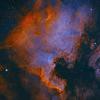
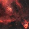
An interesting comparison. I'm surprised that you didn't use a sky flat as a reference to subtract from the others. That would have given you a true flat reference point with no chance of variable illumination that you get from the flat panels.
Another test I've seen done for flat panels is to take flats, rotate the panel 90°, then take flats again. Optical path defects will remain in the sam position, but panel non-uniformities will not. So if you subtract them from each other, you will see the non-uniformities without any confusion from two different panels interacting with each other.
The color balance is also interesting in that it's very different from what I've seen. I have two flat panels, a generic electroluminescent panel, and an LED tracing panel. Comparing the two side by side, the EL panel shows a distinct pinkish color, while the LED appears pretty neutral. In addition, the EL panel needs time to warm up. It is stored outside in an observatory, and when first turned on in cold weather it is dimmer and bluer, and changes color and brightness over time.
One more thing to point out about LED panels. There are different types, with different ways of adjusting brightness, which can affect the uniformity. Some units have the power control circuitry built into the frame. People have reported that these show a glow from the area near that circuitry, possibly due to heat and associated near-IR, which the camera can record.
In addition, as you noted, some use PWM which can produce banding at short exposures. But some (not many) use a straight 12V dc supply and can be varied in brightness simply by adjusting the input voltage. I chose a panel that used DC voltage for control and did not have any power circuitry in the frame. It does not produce banding at any exposure length.
-Dan