Jump to content

  •  

CNers have asked about a donation box for Cloudy Nights over the years, so here you go. Donation is not required by any means, so please enjoy your stay.

Photo

Adventures converting a microscope micrometer to astrometric purposes

Astrometry Equipment
  • Please log in to reply
72 replies to this topic

#51 quesne

quesne

    Vostok 1

  • -----
  • Posts: 145
  • Joined: 01 Mar 2015
  • Loc: Philadelphia, PA

Posted 23 February 2024 - 10:38 PM

—What is the shape of the end of your illuminator, where the led is? I.e., does it point back up towards the eye end, or somewhere else?

As requested, Josephus....some images of the LED illuminator tip under the microscope @ 50 and 100x.  It looks like the LED itself is embedded in some sort of trapezoidal cube.  I guess maybe to focus the beam along five planes? (top, up, down, left, right).  It looks like the side beams would have a somewhat forward angle (i.e. toward the top of the trapezoid).


BTW - I thought it would be nice to have the measurement readings, but I just realized I don't have my stage micrometer handy, so can't calibrate the eyepiece gradations!  Sorry about that :-(


IMG_5130_small.jpg


IMG_5141_small.jpg


IMG_5151_small.jpg


IMG_5165_small.jpg


  • LU1AR and Josephus Miller like this

#52 Josephus Miller

Josephus Miller

    Mariner 2

  • *****
  • topic starter
  • Posts: 279
  • Joined: 16 Feb 2023
  • Loc: PA, USA

Posted 24 February 2024 - 10:25 AM

Thanks! These are interesting, and less directional than I had expected. Good find with these. They’re well suited to the use.
  • quesne likes this

#53 quesne

quesne

    Vostok 1

  • -----
  • Posts: 145
  • Joined: 01 Mar 2015
  • Loc: Philadelphia, PA

Posted 24 February 2024 - 11:47 AM

Last couple of shots, I promise!  I just wanted to clarify for your orientation questions, Josephus.  I'm not very talented when it comes to close-up iPhone shots, so forgive the poor focus!


Here is a view from inside the Barlow body looking down in the same direction as the eyepiece would be situated.  Between the arrows, you can see the tiny little LED lens/crystal peeking out from the edge of the heat-shrink tubing.  It's not facing directly back toward the camera, but it is bent over a little with one of the corners of the trapezoid-crystal pointing almost directly toward the eyepiece field lens:


IMG_5116_small_arrows.jpg


Here is an "off-axis" shot with the LED illuminated:


IMG_5198_small.jpg


Here is an "on-axis" shot from directly below with the LED illuminated.  You can see pretty clearly how the LED hangs over a bit toward the center axis of the eyepiece orafice:


IMG_5191_small.jpg


Of course, I am in no way suggesting that this is the best orientation, angle or distance for the LED.  It's simply the current state of my very preliminary proof-of-concept model.  I'll continue experimenting with all of those factors, as well as the brightness (which I think will be crucial) -- once I get a (plus or minus) 5K potentiometer in the circuit.


Clear skies! :-)


  • R Botero likes this

#54 quesne

quesne

    Vostok 1

  • -----
  • Posts: 145
  • Joined: 01 Mar 2015
  • Loc: Philadelphia, PA

Posted 28 February 2024 - 09:06 PM

Hello All:


There is another aspect of the filar micrometer adaptation -- having nothing to do with illumination -- that we've hardly even touched on in this thread, namely: the addition of a protractor circle.  I've been doing some thinking about it, and a little experimentation/modeling.  I thought I would post a few photos of my efforts to-date, and elicit some feedback from anyone interested.


I created four or five simple mock-ups out of cardboard and paper.  My goal is to work out the details of the various factors before I go to the trouble of 3-D printing one.  There are a few variable factors I am considering: Size, placement, thickness, fit, precision, markings, pointer.  I am sure there are other things I have not even thought of.  BTW - The markings that you see on the paper are NOT necessarily what I would put on the final version.  In most cases, I was really only looking at the outer circle of the scale (I was just too lazy to block the rest out when I printed it).  However....maybe there is some advantage to having multiple scales?  Please chime in if you have an opinion on that :-)


Here are a few pictures of the smaller radius circle with the Leitz Wetzler eyepiece (it has basically the largest body of all the filar's I have available).  FYI - I made a smaller circle than the one pictured here, but it seemed like it could be difficult to read.  The protruding "arc" with the numbers on it was very close-in to the micrometer body.  The other thing I was concerned about was the precision of reading from a practical standpoint.  I am hoping to create a device that will reliably give me at least 30 arc minutes of precision.  That's difficult to do if the circle is too small.


IMG_5210_small.jpg


IMG_5213_small.jpg


IMG_5215_small.jpg


I'm out of room here for attachments, so I will add another post for the larger circle....


  • LU1AR likes this

#55 quesne

quesne

    Vostok 1

  • -----
  • Posts: 145
  • Joined: 01 Mar 2015
  • Loc: Philadelphia, PA

Posted 28 February 2024 - 09:14 PM

Here are a couple of photos with the larger circle.  I think it might be easier to read, and more precise.  I just don't know if it needs to be this big.


BTW - It is probably not apparent in the larger scale photos, but the outer-most ring is calibrated in 30 arc-minute gradations.  That's why I included a zoomed in detail.


IMG_5225_small.jpg


IMG_5232_small.jpg


Marking Detail.JPG


  • LU1AR likes this

#56 Josephus Miller

Josephus Miller

    Mariner 2

  • *****
  • topic starter
  • Posts: 279
  • Joined: 16 Feb 2023
  • Loc: PA, USA

Posted 28 February 2024 - 09:23 PM

Very nice!

Where did you get those scales? I understand they may not be what you use in the end, but they look pretty good from here.

Also, any thoughts on a pointer? Or would you just use the filar body?

#57 quesne

quesne

    Vostok 1

  • -----
  • Posts: 145
  • Joined: 01 Mar 2015
  • Loc: Philadelphia, PA

Posted 28 February 2024 - 10:08 PM

Very nice!

Where did you get those scales? I understand they may not be what you use in the end, but they look pretty good from here.

Also, any thoughts on a pointer? Or would you just use the filar body?

I printed the scales off of some metal and plastic protractor discs available on Amazon, eBay and AliExpress.  Here are the ones I thought were pretty good, but there are others available.


360 degree protractor on Amazon.jpg


360 degree protractor dial 3.JPG


360 degree protractor dial 2.JPG


As for a pointer, that is a great question.  I'm not really sure yet.  I had occurred to me to use something on the micrometer body (like the edge of an immobile knob or a corner of the body).  The problem with that is that I don't think either would be adequate, especially if the precision goal is 30 arc-minutes.  My inclination is to cut a fairly sharp pointer out of heavy-gauge sheet metal, including a large area to glue underneath the micrometer body with CA tape (a large glued area for stability and to resist getting knocked around by my fingers or an errant palm).  That way it will be both stable and removable.  Those are just my thoughts for the moment :-)


  • jmgv68, LU1AR and Josephus Miller like this

#58 quesne

quesne

    Vostok 1

  • -----
  • Posts: 145
  • Joined: 01 Mar 2015
  • Loc: Philadelphia, PA

Posted 01 March 2024 - 01:11 AM

Hello All:


Just wanted to provide a quick update on a slight evolution in my illuminator design.  I was really struck by something you said, Josephus, in post #39 of the other thread ("Creating my own micrometer reticle eyepiece").  You observed that my LED-on-a-stalk design required the light source to be a little off center, leaving some of the reticle to be effectively "in the shade".  This was very true.  Due to the size of the stalk....if I swung it over too far towards the center line, it would certainly begin to obstruct light from getting to the eyepiece.  Consequently, I did some experiments and bent the stalk over more toward the "center" line of the field lens.  The results were impressive.  The reticle was lit up perfectly 360 degrees, but there was still the problem with obstruction.


It occurred to me that, compared to my clunky stalk, the tiny wires of the LEDs by themselves would hardly obstruct the incoming light at all.  I figured if I could "string" them across the entrance of the Barlow -- with the LED suspended right in the middle -- it might solve that problem entirely.  I had already ordered these trim potentiometers and a few of these very inexpensive plastic Barlows from SurplusShed.com in anticipation of building my next model.  So last night I did a proof-of-concept for the "suspended LED" idea.  The $5 Barlows come with a threaded retainer ring on the actual lens.  When the lens is removed, the ring makes a very nice platform to string the wires across.  I included a 100K pot in the circuit this time (hot glued to the body).  The LED is dead center of the barrel, and the potentiometer lets me vary the scale-filum intensity from barely-visible-in-total-blackness, to way-too-bright.


The wires are snaked up through the body and passed the 23.2 inch adapter.  The pot is small, but it's easily adjusted with your fingers (or with a small screwdriver, if you need to).  The Barlows come from the supplier with a nice little cap for the field lens.  So unlike the stalk, my LED is unexposed in use (i.e. inside the Barlow body), and fully protected when the cap is closed :-)  In a final version of this, I will definitely attach the wires much more permanently...and improve on the component connection layout (there's no need, for example, to have the junction box with the extra wire wrapped around it).  Anyway, I am looking forward to the next iteration.  Adding some photos in the next couple of posts.


P.S.  It was too cold to go stand outside tonight, so I took the FOV photo out of my window at a "stand-in DSO" (a very dim driveway light about a quarter mile away).  The intensity of the LED is at the minimum.  I'll post some real star-test photos once the weather is more inviting :-)


My "stand-in DSO"

Filum and scale with standin DSO.JPG


IMG_5372_small.jpg


From the top looking down

IMG_5416_small.jpg


Edited by quesne, 01 March 2024 - 01:17 AM.

  • LU1AR and Josephus Miller like this

#59 quesne

quesne

    Vostok 1

  • -----
  • Posts: 145
  • Joined: 01 Mar 2015
  • Loc: Philadelphia, PA

Posted 01 March 2024 - 01:16 AM

A couple more photos....


IMG_5425_small.jpg


IMG_5432_small.jpg


Very nice protective cap!

5433_smaller.JPG


Edited by quesne, 01 March 2024 - 01:18 AM.

  • LU1AR and Josephus Miller like this

#60 Josephus Miller

Josephus Miller

    Mariner 2

  • *****
  • topic starter
  • Posts: 279
  • Joined: 16 Feb 2023
  • Loc: PA, USA

Posted 01 March 2024 - 06:55 AM

This is a really clever idea, and an elegant evolutionary step from your previous design! The result should be a compact plug-and-play unit that you could use with a filar, a reticle, or anything else needing illumination. The initial results are promising! Looking forward to hearing how it performs under the sky.
  • quesne likes this

#61 quesne

quesne

    Vostok 1

  • -----
  • Posts: 145
  • Joined: 01 Mar 2015
  • Loc: Philadelphia, PA

Posted 03 March 2024 - 02:13 PM

This is a really clever idea, and an elegant evolutionary step from your previous design! The result should be a compact plug-and-play unit that you could use with a filar, a reticle, or anything else needing illumination. The initial results are promising! Looking forward to hearing how it performs under the sky.

Thanks very much, Josephus.  Yeah, I am really looking forward to trying it out on the real stars!  And you're right....a big part of my requirement is that it also work with my home-made astrometric reticle.....or any other microscopy reticle eyepiece that I want to use.


Your comment about the "plug-and-play" aspect is very timely.  I ran into a minor design flaw on that yesterday afternoon, so I re-engineered part of the illuminator last night.  I will post an update.


#62 quesne

quesne

    Vostok 1

  • -----
  • Posts: 145
  • Joined: 01 Mar 2015
  • Loc: Philadelphia, PA

Posted 03 March 2024 - 03:46 PM

This is just a quick update to highlight two important design flaws that I came across yesterday, and my fixes for them.  The flaws became apparent when I was swapping out my home-made astrometric reticle eyepiece and the filar micrometer.  I was trying to compare the differences in brightness of the LED needed for each one.


The biggest problem was that -- since the wires snake all the way up through the body and out the main orifice -- when I swapped out the eyepieces, the sharp outside edges of the Meade eyepiece barrel started to chafe the wires badly.  There was another smaller problem at the field end.  If I was not extremely careful when removing the protective cap, it would turn the Barlow lens cell and begin to stress the LED-to-wire solder points....eventually to the point of breaking.


My solution was to attach the LED wires instead to the interior wall of the barrel (just above the Barlow lens cell threads), and to drill a very small hole in the side of the body right at the top of the 1.25" OD point.  This allows the wires to exit the barrel at a "protected" location, and inoculates them from any interference or stress.  The only additional change needed was to protect the wires along the outside of the barrel with heat-shrink tubing.


Since I was re-soldering and re-gluing anyway, I made three other minor changes that seemed useful, namely: 1) adding a 5K ohm gang of resistors in series to further modulate the potentiometer/brightness; 2) cutting the LED wires shorter and soldering them directly (i.e. no junction block), and; 3) encasing all of the external wires in hot-glue to protect them during normal handling.


Pending some real star testing, the resulting illuminator pretty much fits all the criteria I set out for.  Here are some photos:


Wires attached along barrel wall with CA glue tape

IMG_5532_small.jpg


Red wire crosses over to join the blue wire

IMG_5533_small.jpg


Both wires climb the wall and exit together

IMG_5534_small.jpg


Photos continued in another post.....


  • LU1AR likes this

#63 quesne

quesne

    Vostok 1

  • -----
  • Posts: 145
  • Joined: 01 Mar 2015
  • Loc: Philadelphia, PA

Posted 03 March 2024 - 03:59 PM

Wires exit together through a small hole.  I can now swap out the eyepieces without worrying about chafing anything waytogo.gif

IMG_5540_small.jpg


The hot glue is REALLY ugly but very effective at protecting everything during handling....almost like Han Solo encased in carbonite lol.gif


You can see the short length of heat-shrink tubing carrying the wires up, and one of the resistors over toward the left (light blue with colored lines).

IMG_5515_small.jpg


The added resistance allows a dimmer minimum for the brightness

IMG_5526_smaller.jpg


  • LU1AR likes this

#64 quesne

quesne

    Vostok 1

  • -----
  • Posts: 145
  • Joined: 01 Mar 2015
  • Loc: Philadelphia, PA

Posted 09 March 2024 - 11:34 PM

Hello All:


I posted a new topic in the Double Star forum to discuss "Selecting, Adapting and Using a Microscope Filar Micrometer for Astrometric Measurements".  I started it off with a review of the various micrometers I've tested (17 so far), including some weight and filum/scale orientation data.  It's tangential to the stuff we're discussing here, and I didn't want to hijack your thread, Josephus!  Just an FYI :-)


#65 quesne

quesne

    Vostok 1

  • -----
  • Posts: 145
  • Joined: 01 Mar 2015
  • Loc: Philadelphia, PA

Posted 12 March 2024 - 01:43 AM

Hi Folks:


Just a quick update to let you know I completed my first illuminator star test this evening.  It was cold out, but not too cold :-)  I only spent an hour with the ETX-125 and three of the micrometers (Bleeker, Leitz Wetzlar and Zeiss).  Unfortunately, I was in the parking lot of my apartment building with lights in very close proximity.  Nonetheless, I got some somewhat shaky photos through the micrometers with my iPhone.  Attached below with a few comments.


This is the Leitz Wetzlar trained on a dark patch of sky.  I wanted to see the lowest brightness on the scale and filum with nothing in the background:


Leitz Wetzlar - Dark Sky (cropped - small).jpg


Sirius and HR 2535 through the Leitz Wetzlar.


Leitz Wetzlar - Sirius 1 (cropped - small).jpg


This is the same exact shot as above, but I slipped in the Barlow lens:


Leitz Wetzlar - Sirius 3x (cropped - small).jpg


The Zeiss on Orion Nebula.  From left to right: HR 1887, Nair al Saif and the pair of Theta 2 Orion and Trapezium.  I was anxious to see how well dimmer stars would appear with the LED brightness at a minimum.  It looks pretty good.  I can read the scale even with the bright lights around me.  When my eyes are dark-adjusted, I suspect a lower minimum brightness will work even better.  Measuring the nebula itself is a goal I'm setting for myself.  It will be a good test of visual acuity in observing the gas cloud through LED light.  As it appears to me this evening, though, the nebula is fairly washed out:


Zeiss - Orion Nebula 1 (cropped - small).jpg


One more of the Zeiss on Orion Nebula.  I put the arrows in to show the fila (right along the midline of the FOV).  There is a small fixed vertical line (left side), and a longer moving vertical dashed line (right).  What you can't see in the photos are the two sets of 45 degree fila, their apex at the zero point.  Very strange setup, but I like some aspects of it.  The dual straddle marker at the top is a nice touch for setting the fixed line at the target origin point.  Aside from that, it doesn't help the astronomer much -- at least not with any precision -- since it doesn't intersect the midline.  BTW - Just for reference, the star down at the extreme bottom right edge is HR 1806:


Zeiss - Orion Nebula 2 (cropped - small - arrows).jpg


The Bleeker on Orion Nebula.  HR 1806 is up to the top left in this image:


Bleeker - Orion Nebula (cropped - small).jpg


  • R Botero, LU1AR and Josephus Miller like this

#66 Josephus Miller

Josephus Miller

    Mariner 2

  • *****
  • topic starter
  • Posts: 279
  • Joined: 16 Feb 2023
  • Loc: PA, USA

Posted 12 March 2024 - 11:35 AM

Quesne—nice work. Thank you for the pictures!

Observations:
1. Looks like you had no trouble with the barlow lens in place. I’ve tried that, but it has never been practical because it reduces my brightfield almost to black. Perhaps that is a disadvantage to objective-end illumination. Another point in favor of eyepiece-end illumination.

2. I see I’m not the only one to struggle with schmutz! It seems no matter how much I clean, illumination of the reticle elements inevitably also illuminates even nominal grime.
  • quesne likes this

#67 quesne

quesne

    Vostok 1

  • -----
  • Posts: 145
  • Joined: 01 Mar 2015
  • Loc: Philadelphia, PA

Posted 12 March 2024 - 07:46 PM

Yeah, Josephus. That’s a good point about the Barlow. The quality of the actual lens is very marginal at best (considering it’s a five dollar SurplusShed eyepiece :-)  But it does work fine with virtually no reduction at all in illumination.  I guess with your setup the apparent FOV with the Barlow installed is much narrower, so less of your illumination actually hits the micrometer.


And you’re right….I found that to be pretty annoying about the schmutz!  To be fair, I don’t think I’ve actually cleaned either the Zeiss or the Leitz Wetzlar since they arrived.  But I’m almost positive that I gave the Bleeker a fairly decent cleaning. Looks like there’s a hair or something pretty substantial in there. I’ll have to check it out :-)


#68 quesne

quesne

    Vostok 1

  • -----
  • Posts: 145
  • Joined: 01 Mar 2015
  • Loc: Philadelphia, PA

Posted 17 March 2024 - 03:31 PM

The weather was pretty nice last night -- and the seeing was excellent -- so we spent our evening at a star party on the model airplane field at Valley Forge National Park (our local astro club's dark-sky spot).  I was able to continue testing the illuminator but, for the sake of consistency, I stuck with the Bausch and Lomb filar micrometer during the whole session.  I had a few simple goals:


1.  Observe multiple objects including:

     a.  Jupiter and it's moons

     b.  The Orion Nebula

     c.  Pleiades

     d.  A few individual stars of notably low magnitude

     e.  Andromeda - My son tried to bring it up -- and we may have had a good chance of seeing it -- but it was too low on the horizon and there was a haze starting to form toward the north, so.....next time maybe.


2.  Get some idea for:

     a.  The approximate magnification factor (unlike a telescope EP, these instruments are not labeled with a specific FL value)

     b.  How well I can see nuances and features of some objects with the illuminator on (e.g. Jupiter's bands, Orion's gas cloud, etc.)

     c.  How much lower the minimum brightness settings needs to go, especially given dark-adjusted eyes.


My tests were very subjective.  I have no way of calculating the exact lumens being produced by the LED.  I guess if I was REALLY dedicated, I could....add an ammeter in series into the circuit....and measure the current being drawn....and then calculate the lumens based on the specs...(queue the deep inhale and groan indicating what a complicated and tedious exercise that would be).  But as you've probably already deduced, I am NOT that dedicated ;-)  Since my eyes are basically the "instrument of measure", I'm happy to keep my analysis somewhat subjective for the time being.  I was, however, able to get some halfway decent photos with my handheld iPhone....at least enough to spark some conversation.


The first thing I noticed was that both the Orion gas cloud and Jupiter's bands are much more visible by eye through the EP than the photographs would suggest.  In fact, I would say that -- at the minimum illumination level -- I could confidently set the micrometer zero at one end of the nebula, and set the filum at the opposite extreme....essentially measuring the breadth of the cloud.  I can't make the same statement about Jupiter, but only because I would need to Barlow the micrometer to enlarge the image (I did not have the time to do that).  Suffice it to say that the brightness does not need to be much lower....probably only a little bit.  And when I get the time to complete a full calibration, Jupiter and Orion will be my first test-bed targets.


On the other hand, the photos opened up a really interesting topic of discussion between me and my son.  I have an iPhone holder that attaches to the ocular -- and I would like to document some of my measurements using my iPhone camera.  But the camera would need to "see" the same or similar details that my retina is seeing...so that I have confirmation of the placement of the zero-point and filum.  I am wondering whether the "wash-out" of certain features/colors could be offset or eliminated using software filtering in the NightCap iPhone app, for example.  I am going to post the question in the AP forum one of these days.


As for the magnification, I confess that I did not have the time to start swapping out the filar EP with other fixed FL EPs to figure out where exactly it sits.  Pleiades filled the entire FOV, and even spilled some outside of it.  I would say I could see about 85% of it.  Next time I go out, I'll pay a little more attention to gathering some data for that exercise!  In the meantime, some shaky photos to ponder :-)


Jupiter and it's moons (sorry for the abominable quality of this image; next time I go out I will plan to use my iPhone/camera holder):

IMG_5925_cropped.jpg


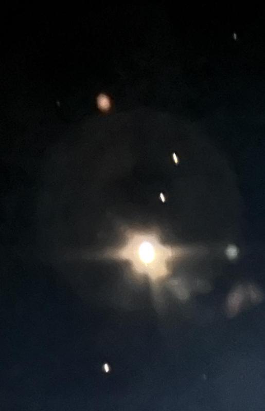
Jupiter and it's moons (with illumination):


IMG_5935_cropped.jpg


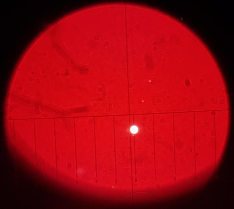
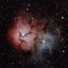
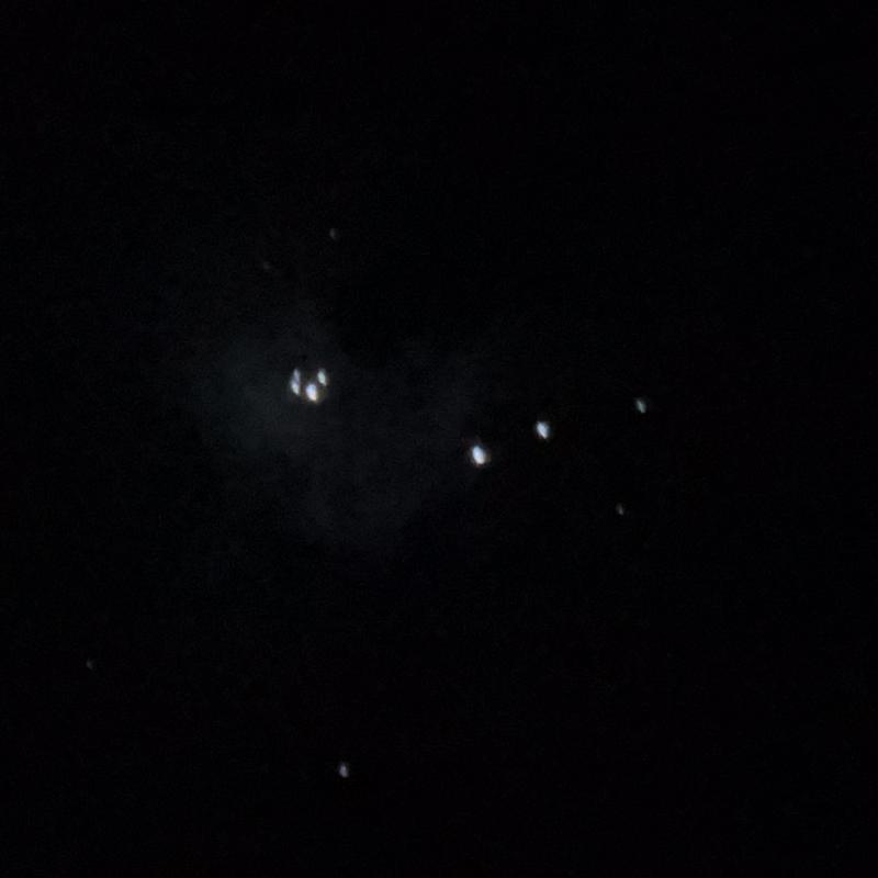
Orion Nebula - The gas cloud is much more visible to my eye in the EP than it is in either of these photos.  Take note of HR 1967 -- a 6 magnitude variable star -- at the extreme bottom.


IMG_5938_cropped.jpg


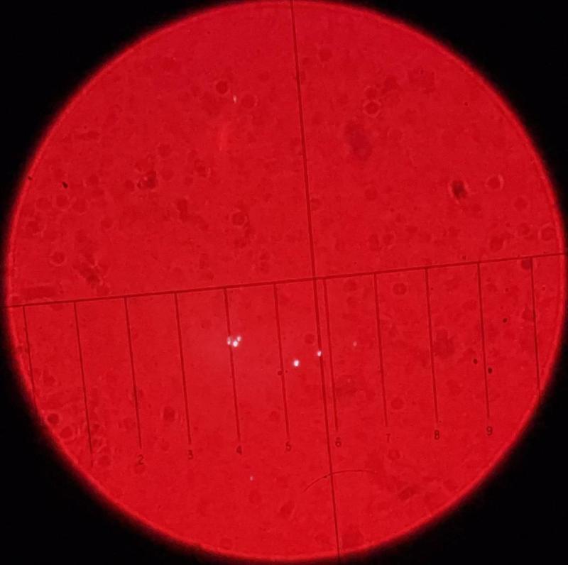
Orion Nebula (with illumination) - HR 1967 is clearly visible at the bottom beneath the #4 scale line:

IMG_5961_cropped_small.jpg


Edited by quesne, 17 March 2024 - 05:49 PM.

  • LU1AR and Josephus Miller like this

#69 quesne

quesne

    Vostok 1

  • -----
  • Posts: 145
  • Joined: 01 Mar 2015
  • Loc: Philadelphia, PA

Posted 02 May 2024 - 09:05 AM

Hello All:


Just a quick FYI: I finished building another illuminator last week (I have been experimenting with alternative components), so I've decided to sell the first working model (you can see the design in the posts above).  It is self-contained (button-cell powered), light and easy to use.  For anyone wanting to use a filar micrometer -- or a microscope (or home-made) reticle eyepiece -- illumination is essential.  This design works with any 1.25" eyepiece, or any microscope-sized eyepiece barrel using an $8 adapter that can be purchased on eBay.


The illuminator is advertised for $45, but I will discount it heavily for anyone on this thread (my material cost per unit is about $22.50 and it takes me about 4 or 5 hours to build one).  Just thought I would mention it here as it could be useful.  Here is a link to the classified post.


Thanks and clear skies :-)


#70 quesne

quesne

    Vostok 1

  • -----
  • Posts: 145
  • Joined: 01 Mar 2015
  • Loc: Philadelphia, PA

Posted 11 May 2024 - 01:49 PM

Updated Reticle Illuminator


Just providing an update regarding my illuminator project.  FYI - I have already posted some of this at the end of a much longer post in the double-star thread "Selecting, Adapting and Using a Microscope Filar Micrometer for Astrometric Measurement".  That post is primarily an update on my evaluation of a series of micrometers that I've been testing, but it also covers some other stuff.


Regarding the "new generation" illuminator, the changes I made provide for a slightly streamlined design and include:


     1. Integrated button cell battery holder (as opposed to the white box hanging on by wires);
     2. Small push-button switch mounted on the side (instead of the slide switch on the battery box);
     3. 1 meg ohm potentiometer, providing a very wide range of illumination, and;
     4. A hole in the protective cap to keep it from slipping off.


Impressions - The button is much more convenient compared to the little battery box.  Your fingers can find it in the dark, allowing you to turn it on and off at will (FYI - Due to the miniscule size of the LED and tiny amount of current it draws, battery power is really not an issue.  I have had one of the batteries on for over 4 hours, and the LED is still very bright).  The potentiometer is ultra sensitive, and allows a wide range of brightness from virtually invisible (unless you are in pitch darkness), to full brightness.  In fact, one use I have already found for it is as a small red flashlight!  The LED is easily bright enough to be useful in that sense, and you can adjust the brightness very finely – even at the high end – using the potentiometer.  The only thing I can think of to complain about regarding the 1 Meg ohm pot is that the brightness control at the very low end is only sensitive for about 50% of the knob’s travel distance.  After that, the brightness jumps up considerably.  I can imagine circumstances where a little more fine control would be helpful.  Likewise, I’ll continue to experiment a little with the resistance value(s).


Below are photos of the Unitron W 10x and Zeiss K 16x with the illuminator on my ETX-90, as well as a couple of close-ups.


IMG_6811_cropped_small.jpg


IMG_6762_cropped_small.jpg


IMG_6659_cropped_small.jpg


IMG_6674_cropped_small.jpg


  • R Botero, LU1AR and Josephus Miller like this

#71 quesne

quesne

    Vostok 1

  • -----
  • Posts: 145
  • Joined: 01 Mar 2015
  • Loc: Philadelphia, PA

Posted 11 May 2024 - 02:00 PM

I ran out of space in the previous post, so I am adding a couple more pictures, including the two illuminated reticles:


IMG_6664_cropped_small.jpg


IMG_6741_cropped_small4.jpg


IMG_6778_smaller_cropped.jpg


  • R Botero, LU1AR and Josephus Miller like this

#72 Josephus Miller

Josephus Miller

    Mariner 2

  • *****
  • topic starter
  • Posts: 279
  • Joined: 16 Feb 2023
  • Loc: PA, USA

Posted 11 May 2024 - 07:57 PM

Quesne, thanks for keeping us up to date. Very nice progress!


  • quesne likes this

#73 MJB87

MJB87

    Fly Me to the Moon

  • *****
  • Moderators
  • Posts: 5,983
  • Joined: 17 Feb 2014
  • Loc: Talbot County, MD & Washington, DC

Posted 12 May 2024 - 06:15 AM

Moving to a more appropriate forum.


CNers have asked about a donation box for Cloudy Nights over the years, so here you go. Donation is not required by any means, so please enjoy your stay.


Recent Topics


Also tagged with one or more of these keywords: Astrometry, Equipment


Cloudy Nights LLC
Cloudy Nights Sponsor: Astronomics