Basically you want a stiff hollow tube with a ratio of about 3:1, no more than 4:1. For you that means a tube about 1m in diameter.
The expensive professional way to do it is build a steel reinforced concrete tube.
A much more economical alternative is to use steel tubes to make a simple truss, just like a truss telescope tube, only heavier. I would be looking at using 100mm steel tube at least, maybe even 150mm. Thinner walled tube with larger diameter is a better use of mass and cost. Either way, lots of welding on the ends, which might get expensive if farmed out to an engineering shop, I don't know what your situation is there. Were I doing it I would make each tube adjustable, either using the turnbuckle principle or at least have threads each end. This is a fairly standard construction technique for modern architectural structures.
If you want to park a car under it then go higher and wider.
Without wishing to dump on all these great ideas I much prefer to work in wood and bolts for rapid later disassembly.
Each construction unit remains manageable by one elderly worker without outside assistance.
Welding isn't going to happen though I have welded in the past.
I am now retired from that area of equipment, expertise and ready access to affordable materials.
Just obtaining tube and profiles is now difficult and expensive here. The former 'outlets' have closed down.
Can't these large diameter concrete tube piers be directly translated into timber with plywood cladding? [Inside and out?}
Lateral stiffness and torque control can be managed by using suitably large dimensions and triangulation.
[Or stressed skin.] Think Pre-WW2 fuselage construction.
Formers, bulkheads, stringers and plywood/canvas cladding held together in vicious dives and rolls.
There are hundred-year-old silos and water tanks just made of timber and planks still standing.
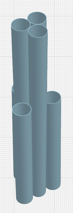
A larger diameter multi-post pier is manageable and can be clad for greater resistance to external excitement.
Make it tapered or conical if you like. Square or round is just as easily put together.
Even nested steel tube with lathes in between can be immensely stiff if made large enough in diameter.
Paper thin aluminium over cardboard honeycomb is an aerospace material or [humbler] internal door.
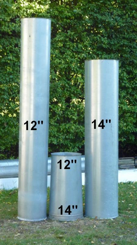
I do have access to some affordable and manageable, seamed, steel ventilation pipe.
It only comes in maximum 14" diameter and usually only in 6'6" lengths.
Larger stuff could still be manageable with my trailer with the tailboard down.
It can be clamped together, end-to-end and guyed or stayed if necessary.
Expanded foam fill with timber or a smaller tubular steel inner reinforcement?
Sandwich or laminated constructions? Who cares if it just takes a bit longer?
The journey is the thing if it leads to useful results.
These are all just ideas I am throwing up in the air to avoid using concrete or concrete blocks.
Doesn't this humble collection of tube [below] stimulate your innate desire to stack one "thing" on top of another?