Homemade folded refractor
#1

Posted 10 February 2005 - 05:36 PM
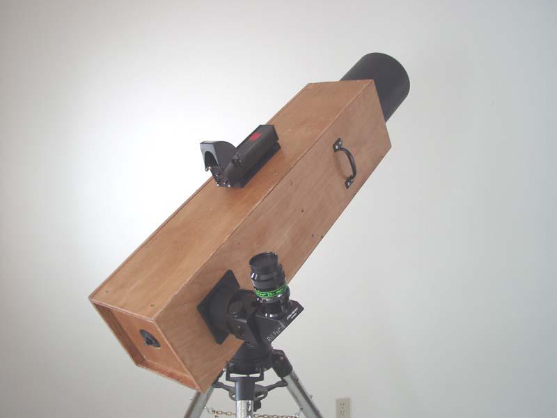
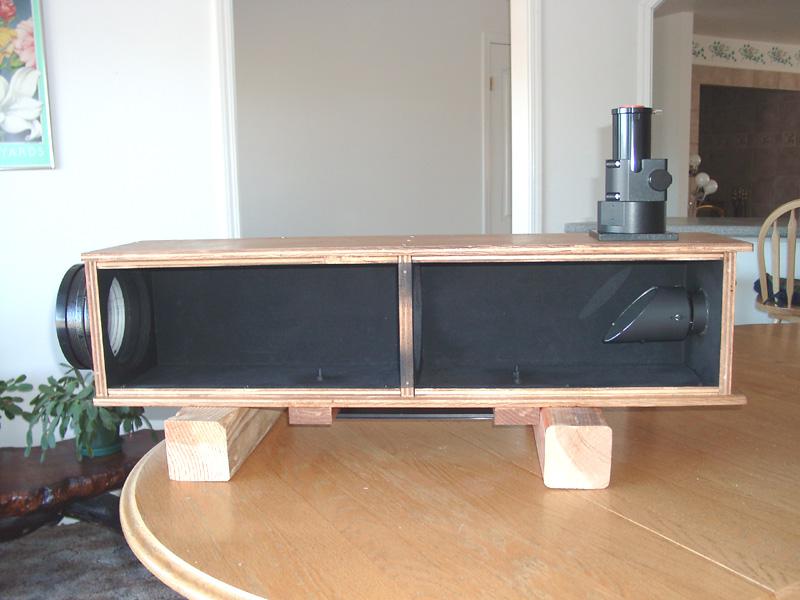
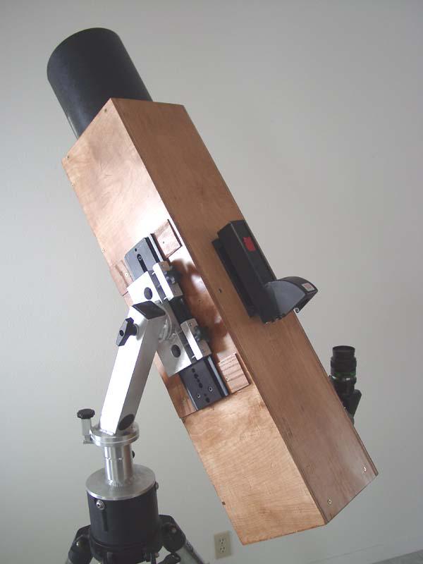
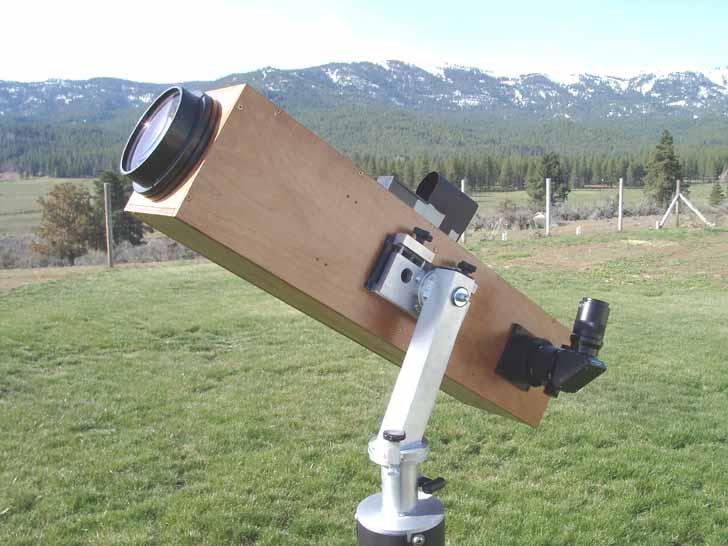
I bought an Orion 120mm f/8.3 last year and was so impressed with the optics that I decided to buy its big brother the 150mm f/8 Synta OTA. The problem was that it was too long to use on my Universal Astronomics UniStar mount (alti azimuth) and too awkward to use at zenith, so I decided to try a new approach by folding the light path and bring it out the side. This was accomplished using a Newtionian secondary mirror (3.1 in) and mirror holder.
This addresses both objectives, reducing the tube length to 36 inches and by the use of a 2 inch diagonal, keeps the eyepiece comfortably oriented throughout the altitude range from horizontal to vertical. The diagonal is rotated in the focuser as the altitude angle is changed, keeping the eyepiece in the same relative position within the 13 inch arc of rotation.
This allows for easy sweeping of the telescope, which is intended for rich field viewing of the Milky Way starfields and also comet searching.
The "tube" is constructed of 1/2 and 3/4 inch birch cabinet plywood, and the interior is completely lined with 3M flocking paper to maximize contrast.
The focuser is a custom MoonLite refractor focuser similiar to the model used to retrofit the 120 and 150mm Syntas. I had it made completely matte black and a flat base to allow mounting to the tube.The inside of the drawtube is lined with flocking paper to completely eliminate unwanted reflections.
The objective is the standard Synta; I hacksawed off the collar that screws onto the tube, retained the lower part of the cell that allows collimation.
The entire tube assembly complete with AP diagonal and 40mm Konig ep and Telrad finder weighs about 28 pounds.
Mr. Bill
#2
 Guest_**DONOTDELETE**_*
Posted 10 February 2005 - 06:00 PM
#3

Posted 10 February 2005 - 06:10 PM
Objective is slightly undercorrected; color is what one would expect from this size and speed achromat. As Synta optics go, this is on the good side of the curve.
Remember, this is NOT intended for planetary or star splitting, but rich field viewing at 30x to 100x.
#4

Posted 10 February 2005 - 07:08 PM
#5
 Guest_**DONOTDELETE**_*
Posted 11 February 2005 - 12:28 AM
Ever thought about building another one and placing them side by side? You'll have a reverse binocular telescope!
#6

Posted 11 February 2005 - 12:51 AM
#7

Posted 11 February 2005 - 12:34 PM
#8
 Guest_**DONOTDELETE**_*
Posted 11 February 2005 - 01:51 PM
#9

Posted 11 February 2005 - 03:06 PM
Mr. Bill
#12

Posted 19 April 2005 - 08:26 PM
Nice work. How do the star tests look (ie. before vs. after the folding?)
I've been interested in doing this for some time and am considering it for my next project. Using Newtonian diagonals just makes a lot of sense. One conern I had was the conventioanl wisdom of keeping the angles small. I want a right angle solution like Mr. Bill. It occured to me that flats should be like most other optics - the errors are predominantly near the edges. I had a conversation with Bryan Greer at ProtoStar about this, and he confirmed it. By using oversized diagonals, the wavefront error is ridiculously small, allowing for large angles and great performance. Looking at the interfeogram on my ProtoStar mirror, I can see it is numerically about 1/17th wave (red light). Qualitatively, I can see almost all of that error occurs at the edge. The center is better by perhaps an order of magnitude. Probably below the ability of the intferogram to measure it.
#13

Posted 19 April 2005 - 09:17 PM
#14
 Guest_**DONOTDELETE**_*
Posted 19 April 2005 - 10:20 PM
-- William
#15

Posted 20 April 2005 - 12:30 PM
#16

Posted 20 April 2005 - 05:49 PM
very cool! i bet you get some curious looks at star parties, huh? looks great!
Thanks! Don't know, haven't been to public starparty since I built it. Had some very positive comments from knowledgeable observers, though.
Thinking of attending the Oregon SP this year and bringing.
Mr. Bill
#17

Posted 20 April 2005 - 07:32 PM
Nice work. How do the star tests look (ie. before vs. after the folding?)
I've been interested in doing this for some time and am considering it for my next project. Using Newtonian diagonals just makes a lot of sense. One conern I had was the conventioanl wisdom of keeping the angles small. I want a right angle solution like Mr. Bill. It occured to me that flats should be like most other optics - the errors are predominantly near the edges. I had a conversation with Bryan Greer at ProtoStar about this, and he confirmed it. By using oversized diagonals, the wavefront error is ridiculously small, allowing for large angles and great performance. Looking at the interfeogram on my ProtoStar mirror, I can see it is numerically about 1/17th wave (red light). Qualitatively, I can see almost all of that error occurs at the edge. The center is better by perhaps an order of magnitude. Probably below the ability of the intferogram to measure it.
That's why I used a 3.1 inch (oversize) 1/15 wave secondary for my relay mirror. You hit it exactly!
#18

Posted 06 March 2007 - 02:21 PM
#19

Posted 06 March 2007 - 06:40 PM
Jess Tauber
#20

Posted 06 March 2007 - 07:17 PM
My first step was to purchase PVC pipe and mount the cell and a focuser to verify the focal length. I also noted the focuser position for the eyepiece in my collection that has the most inward focuser travel (a 31 Nagler).
With focal length and the most inside focuser position confirmed I used a drafting program to lay my project out. I could have used paper and pencil too.
First, you want to draw a cone. The base of the cone is equal in size to the aperture of your lens. The height of the cone is equal to the focal length of the lens. When you place the focuser on the drawing, you want to be sure that the vertex (tip) of this cone is in the center of your focuser drawtube travel.
Second, decide how large of an 100% illuminated circle you need at focus. As a visual obersever, I decided that 1/2" was adequate (more than adequate actually). I then drew a 1/2" line centered on the tip of the vertex, and perpendicular to the light path. I then drew lines connecting each end the of the 1/2" line to the base of the cone (representing the objective lens) on the same side. This gives you a somewhat bigger cone with a "snipped" tip. Anything you place in the scope (mirrors and baffles) should be large enough to accomodate the larger cone.
Third, check what size mirror you have available . Lets say for example you choose a 2" minor axis newtonian diagonal. You want to place that mirror in such a way that the light cone doesn't touch the outer edges of the mirror. For my project, I decided that I would not use the outer 0.15" edge. So I placed the mirror at the point where the cone was only 1.7" wide.
Takes much longer to explain than do. Fire up a drawing program and give it a try.
#21

Posted 06 March 2007 - 08:50 PM
Thanks. It also provided an answer on where to place the focuser draw tube so it accommodates the EP's. My Newtonian's will benefit from that too!
Art
#22

Posted 07 March 2007 - 01:33 PM
#23

Posted 15 March 2007 - 09:47 PM
I'm serious about building this type of scope and ordered a 127mm f/8 Antares, 2" Antares focuser, and Meade 1.8" secondary from the outlet. Still need a diagonal. I just want to know what I'm in for before bouncing the light an extra time
#24

Posted 15 March 2007 - 10:37 PM
or is there something more to this than I'm seeing?
#25

Posted 15 March 2007 - 10:52 PM


