Do ensure, before the pier is encased, that there is no solid contact with adjoining house structure - any such close points better wrapped in insulation quilt to ensure no solid falling debris get trapped there to transfer house vibration to the pier.
What scope have you in mind - for visual or imaging ? Good luck 
Thats great advice! This is the second house I've built and its amazing what can get left in the walls - coke cans, burger king bags, small pieces of wood, broken saw blades, yadda yadda. I have a project manager on site who so far is doing a good job of keeping everything clean - I'll tell him to be alert.
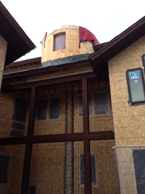
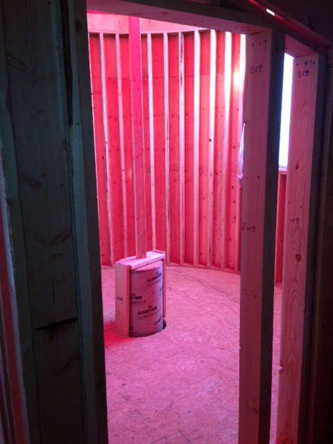
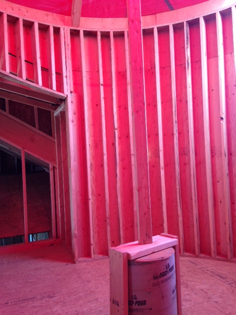
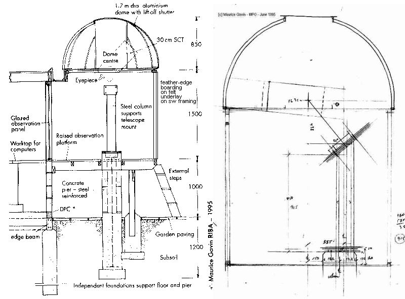
I plan for the curved section of wall (to cover the pier) that will be added on the home's interior - to be built as the home's exterior wall. This way the outer wall that covers the pier is just cosmetic. The small area between the pier and covering walls will be loosely filled with fiberglass batting. That should keep debris from being a problem. The rest of the home will have spray foam insulation.
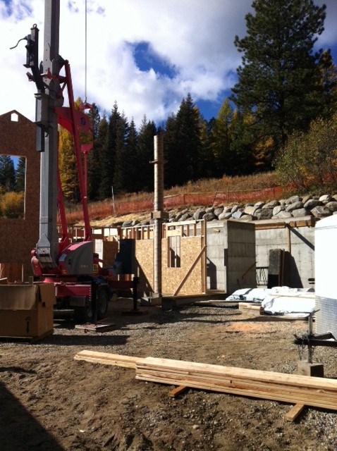
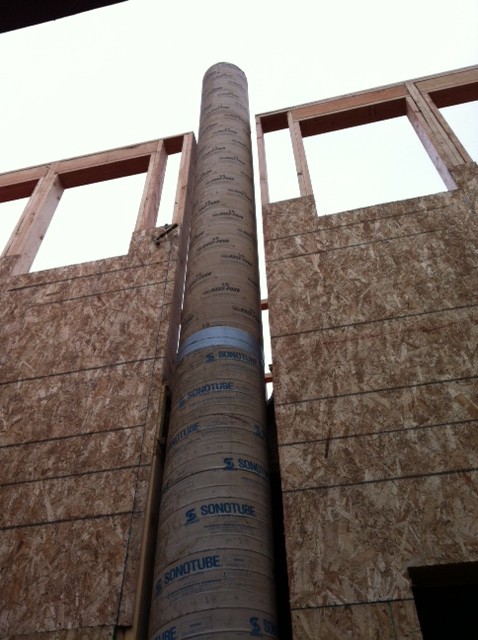
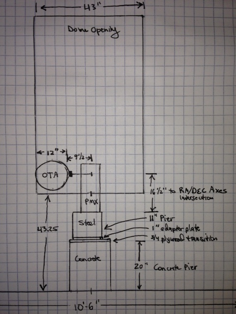
The structural engineer for the project designed the pier - and it was a first for her - just as it was for me. The pier is very slender (16" diameter) as you say - but I found that its extreme height gives it so much volume and mass that it takes a lot to make it move. I would like a bigger diameter but there is now a darn house in the way

And thanks for the good luck wish - I am the designer/builder (but not an architect or contractor) of the home - and I will own all of the mistakes. But I learned long ago that are always a million reasons not to do something - so I make the best choices I can and get on with things and get 'em done
Some luck always helps.
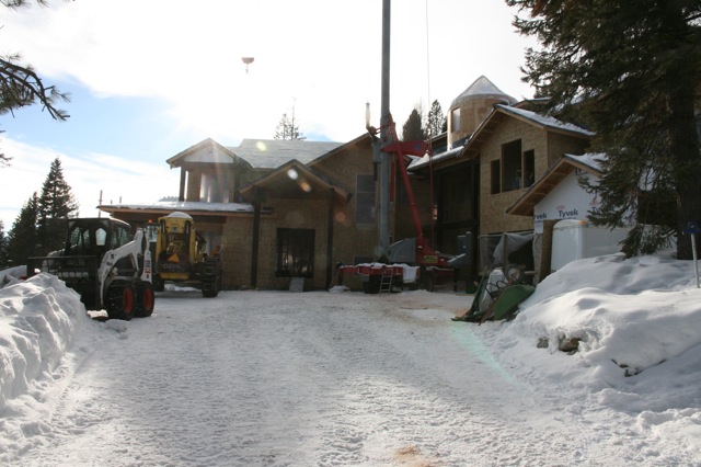
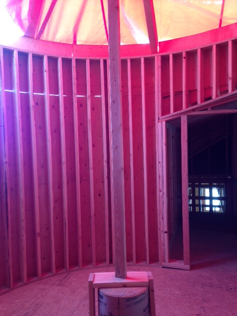
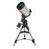
To answer your question - I have not yet decided on a scope or mount. I had to give the structural engineer who designed the pier some size/weight guidlines for equipment early on - so I gave her specs on some well known big stuff. With a 10'6" dome and pier exactly in the center I can't do anything crazy big, but I have plenty of options. I'm working on that today since the lead times on this kind of equipment coincides roughly with the completion date for the home/obs. I am lucky(?) that my wife wants me to get some very nice equipment. I am relatively new to the hobby but don't do much visual observing. I am leaning toward an AP or Paramount mount and a Planewave or Hyperion scope. I like solar observing and have a Lunt 80mm to accommodate somehow. And I like what is happening with the Mallincams.
Also, beneath the obs is a deck - such that half of the obs is over open space below. I will also be designing some simple plenums with fans. The idea will be to open the dome and use these fans to pull outside air down through the slot and exhaust it below the obs. This to equalize inside/outside temps.