
Concise thread about autocollimators+improvements
Started by
Jason D
, Jan 01 2010 12:21 AM
434 replies to this topic
#176

Jason D
-

-
topic starter
- Posts: 7,473
- Joined: 21 Oct 2006
Fly Me to the Moon
Posted 06 February 2010 - 11:35 AM
You can see how my old center spot placement by the factory was off by around 1.5mm. If you purchased quality collimation tools but have no plans to replace the center spot, at least check the placement of the existing spot. In my case, my original stock mirror center spot placement would have introduced 0.75mm PAE.

#177
Starman1
-
-

- Posts: 65,365
- Joined: 23 Jun 2003
Stargeezer
Posted 06 February 2010 - 11:55 AM
Jason,
Jim HAS offered triangles of different sizes, and does recommend different triangle sizes based on focal length.
Jim HAS offered triangles of different sizes, and does recommend different triangle sizes based on focal length.
#178
CatseyeMan
-
-

-

- Posts: 608
- Joined: 16 Dec 2004
Vendor (Cats Eye Collimation)
Posted 06 February 2010 - 12:12 PM
Jason,
Jim HAS offered triangles of different sizes, and does recommend different triangle sizes based on focal length.
Don,
Half of what you said is true. I do offer a "smaller" triangles for the 1.25" Cheshire (smaller ring ID). The "larger" triangles are for the 2" Cheshire tools (BLACKCAT & TELECAT). In each case, they are all the same triangle size (only 2 sizes offered) with varying hole perforation size (or solid) options.
#179
Jason D
-
-
topic starter
- Posts: 7,473
- Joined: 21 Oct 2006
Fly Me to the Moon
Posted 06 February 2010 - 12:17 PM
Jason,
Jim HAS offered triangles of different sizes, and does recommend different triangle sizes based on focal length.
I thought Jim offered different perforation sizes which is different from what we are talking about.
The different triangle sizes are for different focuser sizes -- not different focal lengths.
http://www.catseyeco...om/spotsbig.jpg
Jim, please clarify.
EDIT: I just noticed that Jim has responded while I was working on this reply
#180
Jason D
-
-
topic starter
- Posts: 7,473
- Joined: 21 Oct 2006
Fly Me to the Moon
Posted 07 February 2010 - 12:10 AM
Attached is an animation showing how P+2 stacking is more accurate with the HotSpot compared to the triangle.
Note how it is easier to discern the unstacking of P+2 using the Hospot compared to the triangle spot even though both are shifted by the same amount.
Note how it is easier to discern the unstacking of P+2 using the Hospot compared to the triangle spot even though both are shifted by the same amount.
Attached Thumbnails

#181
Jason D
-
-
topic starter
- Posts: 7,473
- Joined: 21 Oct 2006
Fly Me to the Moon
Posted 07 February 2010 - 12:11 AM
Attached is an animation showing how the Hotspot is more accurate than the triangle when used with the cheshire.
The first frame with only the triangle includes a residual PAE error which is hard to see; however, the same amount of residual error is easily discernable with the Hotspot.
The first frame with only the triangle includes a residual PAE error which is hard to see; however, the same amount of residual error is easily discernable with the Hotspot.
Attached Thumbnails

#182
Jason D
-
-
topic starter
- Posts: 7,473
- Joined: 21 Oct 2006
Fly Me to the Moon
Posted 07 February 2010 - 03:20 AM
Night test passed with flying colors.
The yellow color of the Hotspot did very well under the red light in a dark room.
Note I intentionally unstacked P+2 in the photo.
The yellow color of the Hotspot did very well under the red light in a dark room.
Note I intentionally unstacked P+2 in the photo.
Attached Thumbnails
#183
Jason D
-
-
topic starter
- Posts: 7,473
- Joined: 21 Oct 2006
Fly Me to the Moon
Posted 07 February 2010 - 03:28 AM
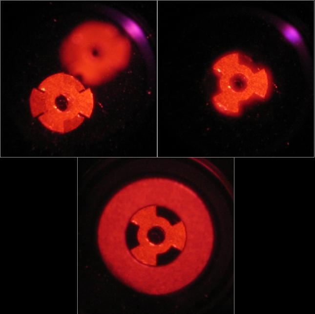
I also ran the maximum residual error test and again Hotspot passed. Any PAE of 0.5mm or above will be detected.
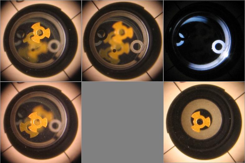
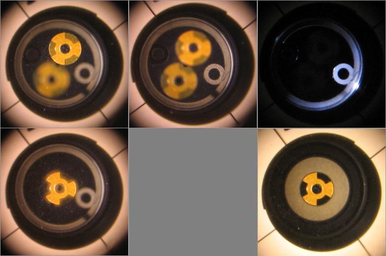
The top row is for a setup where the focuser axis is parallel to the primary axis at a 0.8mm distance.
1- Note how reflection 2 is visible via the central pupil which is our cue that proper collimation has not been met.
2- Note how reflections P&2 are nicely stacked from both pupils -- that is, there is no P+2 parallax.
The bottom row is for a setup where the focuser axis is parallel to the primary axis at a 0.4mm distance.
1- Note how reflection 2 is mostly invisible which could be missed. In this case, this setup might pass the collimation test with 0.4mm PAE but that is within the XLK spec.
Actually, because of the larger surface area of the Hotspot, reflection 2 ghostly image can be seen with a trained eye even at 0.4mm PAE which means that Hotspot should help attaining more accurate collimation when using the XLK alone.
Attached Thumbnails
#184
Jason D
-
-
topic starter
- Posts: 7,473
- Joined: 21 Oct 2006
Fly Me to the Moon
Posted 20 February 2010 - 02:24 AM
If you have a BLACKCAT cheshire and an XLK INFINITY autocollimator you might be interested in this post.
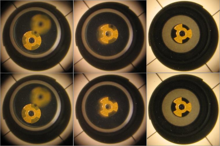
Below are alternative steps to collimate with the BLACKCAT and XLK.
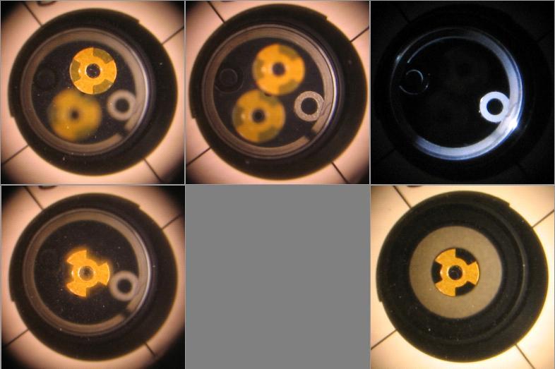
In the attachment, the first column photos were taken from the central XLK pupil. The second column photos were taken from the offset XLK pupil. The third column photos were taken from the BLACKCAT pupil.
STEP 1 (row#1): Use whatever means and tools to collimate other than the autocollimator. In the top row photos I intentionally started with a relatively bad collimation setup.
STEP 2 (row#2): Insert the XLK then adjust the secondary mirror to stack P+2 reflections via the offset pupil.
STEP 3 (row#3): Insert the BLACKCAT then adjust the primary mirror to align P+Ring reflections.
STEP 4 (row#4): Re-insert the XLK then adjust the secondary mirror to stack P+2 reflections one more time.
STEP 5 (row#4): Re-insert the BLACKCAT and evaluate. If you are happy with the cheshire view then you are done.
STEP 6 (row#5): Optional: If you are unhappy with the cheshire view then you can re-iterate one more time. Note the differences between rows 5 and 6 photos are very subtle.
In summary:
1 XLK: Stack P+2 via offset pupil by adjusting secondary
2 BLACKCAT: Align P+Ring by adjusting primary
3 XLK: Stack P+2 via offset pupil by adjusting secondary – a repeat
It is a good idea to re-insert the BLACKCAT and evaluate.
Jason
EDIT:
Clarification: The above 3 steps work for me most of the time without additional iterations when the XLK is used to perfect a decently collimated setup. Because starting setups typically have larger FAE than PAE, I start off with the secondary mirror adjustment to expedite collimation convergence.
Below are alternative steps to collimate with the BLACKCAT and XLK.
In the attachment, the first column photos were taken from the central XLK pupil. The second column photos were taken from the offset XLK pupil. The third column photos were taken from the BLACKCAT pupil.
STEP 1 (row#1): Use whatever means and tools to collimate other than the autocollimator. In the top row photos I intentionally started with a relatively bad collimation setup.
STEP 2 (row#2): Insert the XLK then adjust the secondary mirror to stack P+2 reflections via the offset pupil.
STEP 3 (row#3): Insert the BLACKCAT then adjust the primary mirror to align P+Ring reflections.
STEP 4 (row#4): Re-insert the XLK then adjust the secondary mirror to stack P+2 reflections one more time.
STEP 5 (row#4): Re-insert the BLACKCAT and evaluate. If you are happy with the cheshire view then you are done.
STEP 6 (row#5): Optional: If you are unhappy with the cheshire view then you can re-iterate one more time. Note the differences between rows 5 and 6 photos are very subtle.
In summary:
1 XLK: Stack P+2 via offset pupil by adjusting secondary
2 BLACKCAT: Align P+Ring by adjusting primary
3 XLK: Stack P+2 via offset pupil by adjusting secondary – a repeat
It is a good idea to re-insert the BLACKCAT and evaluate.
Jason
EDIT:
Clarification: The above 3 steps work for me most of the time without additional iterations when the XLK is used to perfect a decently collimated setup. Because starting setups typically have larger FAE than PAE, I start off with the secondary mirror adjustment to expedite collimation convergence.
Attached Thumbnails
#185
Jason D
-
-
topic starter
- Posts: 7,473
- Joined: 21 Oct 2006
Fly Me to the Moon
Posted 20 February 2010 - 03:17 AM
Referring to these earlier posts
Below FP
Above FP
The attachment shows how the Hotspot helps in comparing reflections P & 2 sizes. It is recommended to rack the focuser in or our until both reflections have similar size with no discernable parallax from both of the XLK pupils.
Left photo was taken when the XLK was placed around 3%FL below FP and the right photo was taken when the XLK was placed around 6%FL above the FP. A 2" extension tube was used to elevate the XLK 6% above the FP.
Attached Thumbnails
#186
Jason D
-
-
topic starter
- Posts: 7,473
- Joined: 21 Oct 2006
Fly Me to the Moon
Posted 20 February 2010 - 03:22 AM
As a testament to JimFly’s POVRay simulation accuracy as depicted in the following post
Above FP
I used a 2” extension tube to elevate the XLK 5%FL above the FP then adjusted the secondary mirror to match Jim’s reflection positions. Finally, I created an animated GIF file. I was amazed how the real photo matched the simulation rendering photo.
Jason
Above FP
I used a 2” extension tube to elevate the XLK 5%FL above the FP then adjusted the secondary mirror to match Jim’s reflection positions. Finally, I created an animated GIF file. I was amazed how the real photo matched the simulation rendering photo.
Jason
Attached Thumbnails

#187
Nils Olof Carlin
-
-

-

- Posts: 2,227
- Joined: 26 Jul 2004
Vanguard
Posted 20 February 2010 - 10:37 AM

Nils Olof
#188
Jason D
-
-
topic starter
- Posts: 7,473
- Joined: 21 Oct 2006
Fly Me to the Moon
Posted 20 February 2010 - 11:42 AM
Same setup but with the camera focus set at infinity.
Note the offset pupil has two background reflections. The second background reflection (which is larger) can only be seen when the AC mirror is significantly away from the focal plane.
Note the offset pupil has two background reflections. The second background reflection (which is larger) can only be seen when the AC mirror is significantly away from the focal plane.
Attached Thumbnails
#189
Jason D
-
-
topic starter
- Posts: 7,473
- Joined: 21 Oct 2006
Fly Me to the Moon
Posted 20 February 2010 - 11:44 AM
Nils Olof
Nils Olof, compliments from you are always special :flower:
Jason
#190
Jason D
-
-
topic starter
- Posts: 7,473
- Joined: 21 Oct 2006
Fly Me to the Moon
Posted 22 February 2010 - 12:26 AM
I have verified after countless experiments that if the AC mirror is within 1%FL from the focal plane, both P+2 parallax and size difference is indiscernible visually. At 1.5%FL the difference will barely start becoming discernable.
The 1%FL for my 1200mm scope translates roughly to +-0.5” which is a generous range.
The recommendation to position the AC mirror close to the focal plane is not restricted to the XLK P+2 stacking. It is also recommended for the XL since moving the AC mirror significantly away from the focal plane will change the relative sizes and fuzziness of all reflections and will start introducing small residual errors.
It should be relatively easy to position the AC mirror close to the focal plane with the Hotspot as was shown earlier by comparing the relative sizes of reflections P & 2. If you have the XL, decollimate the primary then stack P+2 to compare their relative sizes as you rack the AC up and down. My suggestion is:
1- Rack the AC in until reflection 2 just starts getting larger than reflection P -- then stop.
2- Rack the AC out until refelction 2 just starts getting smaller than reflection P -- then stop.
Position the AC in the middle of the above range. The above is a one time experiment.
You need to decollimate the primary for the XL to keep reflection 2 visible. If you have the XLK then there is no need to decollimate – just use the offset pupil.
As you rack the AC in and out, you might notice that P+2 will start to unstack. This could be due to mechanical imperfection of the focuser but could also be due to residual errors introduced as the AC mirror moves away from the focal plane. The latter is more detectable for scopes with shorter focal lengths since the focuser travel range makes up a larger percentage of the focal lengths compared to scopes with larger focal lengths.
For imaging scopes, the focal plane could reside above a fully-racked focuser which means the AC mirror can’t be brought close to the focal plane. A 2” extension tube might be handy to position the AC mirror close to the focal plane. See attachment.
Attached Thumbnails
#191
Jason D
-
-
topic starter
- Posts: 7,473
- Joined: 21 Oct 2006
Fly Me to the Moon
Posted 22 February 2010 - 12:27 AM
I finally got to use the XLK+CAM with the Hotspot. Attachment is a starting point for am intentional badly collimated setup. I was concerned the Hotspot reflections in the XLK+CAM will be overwhelming. This was not the case though the view was busier compared to the triangle center spot.
Top row photos were taken from the offset pupil
Bottom row photos were taken from the central pupil XLK+CAM and the BLACKCAT cheshire. The bottom row photos are provided for reference. Neither the central pupil nor the BLACKCAT were used to collimate in the following two posts.
Top row photos were taken from the offset pupil
Bottom row photos were taken from the central pupil XLK+CAM and the BLACKCAT cheshire. The bottom row photos are provided for reference. Neither the central pupil nor the BLACKCAT were used to collimate in the following two posts.
Attached Thumbnails
#192
Jason D
-
-
topic starter
- Posts: 7,473
- Joined: 21 Oct 2006
Fly Me to the Moon
Posted 22 February 2010 - 12:28 AM
Attached photos where taken after one collimation round of XLK+CAM. The collimation round included:
1- Stacked P+2 pupil by adjusting the secondary mirror. If initial collimation is bad, it is possible to use the central pupil to stack P+2 if it is easier visually.
2- Made a mental note of the CAM unstacked image then adjusted the primary mirror to rotate the CAM unstacked image by 180 degrees (for more info, refer to 6 consecutive posts starting from post#3098491 in the following page)
3- A repeat of step#1 but you have to use the offset pupil to stack P+2
The above 3 steps transferred the badly collimated setup to one with good axial alignment.
Note: You can see CAM crescent which represents as small residual error. If you look hard you should also see the same small residual error in the BLACKCAT view.
Attached Thumbnails
#193
Jason D
-
-
topic starter
- Posts: 7,473
- Joined: 21 Oct 2006
Fly Me to the Moon
Posted 22 February 2010 - 12:28 AM
Attached photos were taken after fine tuning collimation by iterating between the CAM and stacking P+2.
Attached Thumbnails
#194
Jason D
-
-
topic starter
- Posts: 7,473
- Joined: 21 Oct 2006
Fly Me to the Moon
Posted 22 February 2010 - 12:29 AM
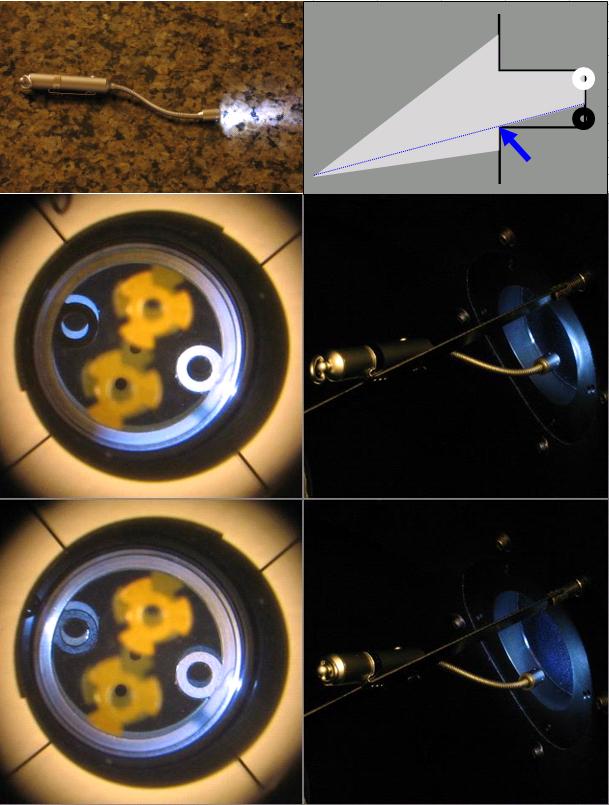
Now I am illuminating the CAM using a clip-on flex-neck LED provided by Jim Fly. The flex-neck allows me to position the LED in such a way to only illuminate the reflective donut of the CAM by using the bottom edge of the focuser to block LED light from the dark non-reflective donut of the CAM. Doing so also moves the LED direct light out-of-view – will not shine on your eye. Adjusting the flex-neck LED is a one time task. See top row photos of the attachment.
Middle row photos were taken with the flex-neck LED light properly positioned.
Bottom row photos were taken with the flex-neck LED light improperly positioned by illuminating both donuts.
The one thing I did not like about this particular flex-neck LED model is its pocket clip-on. Clipping it to the spider vane is OK but not secured enough for my taste. There is the potential of striking it accidently while my hand is busy adjusting the secondary mirror which means it might fall on the primary mirror.
The flex-neck LED is a good solution for the CAM providing it is held more securely to the spider vanes.
Attached Thumbnails
#195
jm510227
-
-

- Posts: 106
- Joined: 02 Dec 2006
Vostok 1
Posted 06 March 2010 - 04:19 PM
Hi Jason:
I have been talking to Jim Fly about when he will be offering the XLK + CAM units for sale, and, in his last note to me (dated 2/21) he said you were evaluating a promising illumination hardware set that he thought you would be reporting on "in a few days" on CN.
I am a relative newcomer to this thread and may have missed your post. if I have missed your posts my apologies for asking you to repeat yourself.
Can you give me (us) an update on where you stand on your evaluation.
Thanks in advance,
Jim Miller
#196
Jason D
-
-
topic starter
- Posts: 7,473
- Joined: 21 Oct 2006
Fly Me to the Moon
Posted 07 March 2010 - 12:41 AM
Hello Jim,
Jim Fly was referring to the Flex-neck LED light shown right above your post. I liked the Flex-neck feature but I am little concerned about the pocket-clip. The clip is not reliable enough to avoid accidentally dropping the LED light in the OTA.
Jason
Jim Fly was referring to the Flex-neck LED light shown right above your post. I liked the Flex-neck feature but I am little concerned about the pocket-clip. The clip is not reliable enough to avoid accidentally dropping the LED light in the OTA.
Jason
#197
Jason D
-
-
topic starter
- Posts: 7,473
- Joined: 21 Oct 2006
Fly Me to the Moon
Posted 07 March 2010 - 12:20 PM
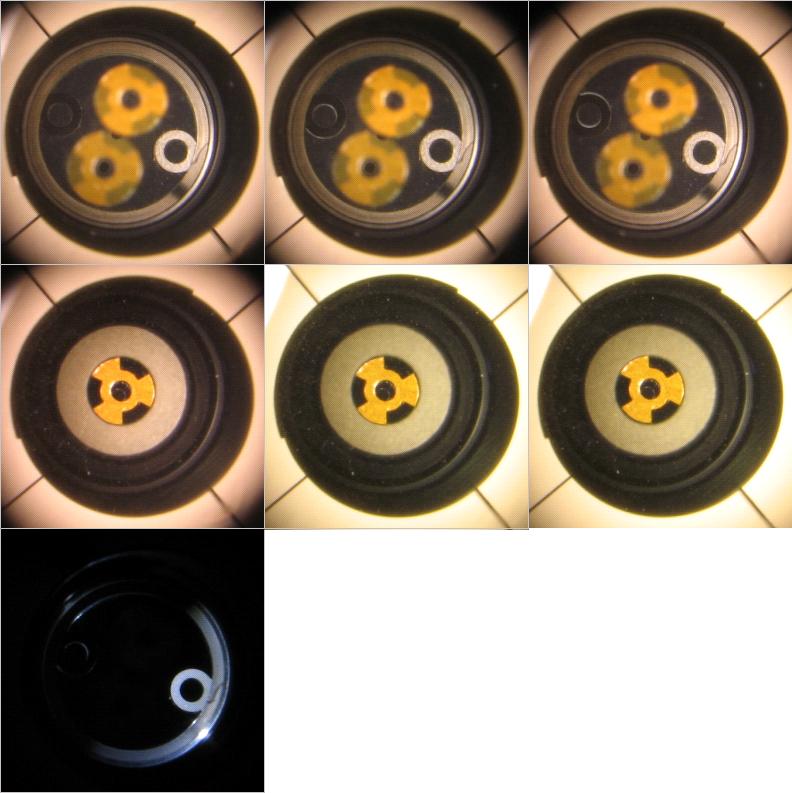
For indoors or outdoors daytime collimation, the CAM produces great results without any special light attachments. By pointing the OTA optimally with respect to any light source, you can use the edge of the OTA opening to reduce illumination on the dark side of the CAM to improve contrast. Just point the OTA around the source light (not directly at it) monitoring illumination at the bottom edge of the AC barrel reflection. Stop when the differential in illumination between any opposite sides of the AC is maximized. Rotate the AC to position the reflective CAM donut on the brightest side and the dark CAM donut on the dimmest side for maximum contrast. I suppose you could also move the light source and leave the OTA stationary -- of course, if that light source is moveable.
See attachment. First column photos are the result of a typical collimation session using the above technique. Note how the reflective donut of the CAM is positioned on the brighter side of the AC. The cheshire confirmed the good results. I used the flex-neck LED to check on the CAM stacking. It was not exact. The contrast I get from the room light will never rival the contrast I get from the flex-neck LED in the dark. Nonetheless, the cheshire view was good.
Then I slightly uncollimated the primary mirror until a CAM crescent became clear as shown in the center column. Then I did the same in the opposite direction as shown in the column. I included the cheshire views at these two opposite points.
Bottom line: Using the XLK+CAM indoors or outdoors at daytime will yield comparable results to using a cheshire without the need for any special light attachment.
Note: Since using the CAM assumes good P+2 stacking, using the "Hotspot" in the above setup was a plus.
Jason
Attached Thumbnails
#198
Jason D
-
-
topic starter
- Posts: 7,473
- Joined: 21 Oct 2006
Fly Me to the Moon
Posted 08 March 2010 - 04:08 AM
My skills in using the XLK+CAM have been improving over the past months. Now I can achieve a high degree of collimation accuracy without the need for any light attachments while collimating indoors or outdoors during daylight. It all comes down to:
1- Positioning the light source properly to increase the CAM contrast.
2- Learning how to best stack P+2 and CAM
3- Understanding how to reduce the number of iterations between stacking P+2 and CAM.
Bottom line: The XLK+CAM in its current form can be used effectively while collimating indoors or outdoors during daylight- there is no need for light attachments.
I am still working on figuring out the best method to illuminate both P+2 and CAM stacks with only one source light.
Attached photos come from an indoors collimation I completed very carefully without using any clip-on light, without a cheshire, and without using the central AC pupil. I took the XLKC cenral pupil and cheshire photos for reference after collimation was completed.
Jason
Attached Thumbnails
#199
Jason D
-
-
topic starter
- Posts: 7,473
- Joined: 21 Oct 2006
Fly Me to the Moon
Posted 29 March 2010 - 01:59 AM
After spending a significant amount of time analyzing and improving the steps for XLK+CAM, I have reached the end of this journey. Here are my final thoughts about the XLK+CAM versus XLK+BLACKCAT
Positives:
1- XLK+CAM is more accurate than the XLK alone.
2- XLK+CAM is a one-tool-solution capable of achieving accuracies better than 0.25mm for both the focuser and the primary axial alignments. That is, the XLK+CAM+HOTSPOT can match the accuracy of the XLK+BLACKCAT+HOTSPOT.
Check the following photos:

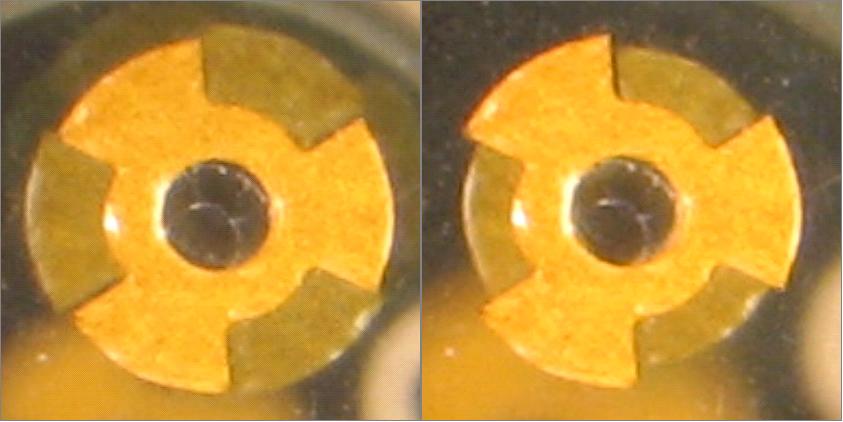
The top row photos illustrate a case with passing XLK visual cues though the CAM and the cheshire visual cues clearly indicate the existence of residual errors – around 0.4mm FAE and PAE in the photos. Because P+2 are stacked with high precision assisted by the HotSpot, the PAE (cheshire) and CAE (CAM) errors will be equal as shown in the following photos which are blown ups from the previous photos. See how both the CAE and PAE have the same direction and the same magnitude.

Negatives:
1- The level of skills needed for the XLK+CAM is more demanding than XLK+BLACKCAT. That is, XLK+CAM is harder to use than XLK+BLACKCAT
2- With the XLK+CAM, both FAE and PAE need to be eliminated to achieve precise axial alignment. With the XLK+BLACKCAT, the user has the option to eliminate PAE without the need to eliminate FAE.
I thought of new ideas and modifications of existing ideas to add a cheshire-like capability to the XLK; unfortunately, none of these “cheshire” ideas can match the accuracy of the BLACKCAT+HOTSPOT.
Positives:
1- XLK+CAM is more accurate than the XLK alone.
2- XLK+CAM is a one-tool-solution capable of achieving accuracies better than 0.25mm for both the focuser and the primary axial alignments. That is, the XLK+CAM+HOTSPOT can match the accuracy of the XLK+BLACKCAT+HOTSPOT.
Check the following photos:
The top row photos illustrate a case with passing XLK visual cues though the CAM and the cheshire visual cues clearly indicate the existence of residual errors – around 0.4mm FAE and PAE in the photos. Because P+2 are stacked with high precision assisted by the HotSpot, the PAE (cheshire) and CAE (CAM) errors will be equal as shown in the following photos which are blown ups from the previous photos. See how both the CAE and PAE have the same direction and the same magnitude.
Negatives:
1- The level of skills needed for the XLK+CAM is more demanding than XLK+BLACKCAT. That is, XLK+CAM is harder to use than XLK+BLACKCAT
2- With the XLK+CAM, both FAE and PAE need to be eliminated to achieve precise axial alignment. With the XLK+BLACKCAT, the user has the option to eliminate PAE without the need to eliminate FAE.
I thought of new ideas and modifications of existing ideas to add a cheshire-like capability to the XLK; unfortunately, none of these “cheshire” ideas can match the accuracy of the BLACKCAT+HOTSPOT.
#200
Jason D
-
-
topic starter
- Posts: 7,473
- Joined: 21 Oct 2006
Fly Me to the Moon
Posted 29 March 2010 - 02:01 AM
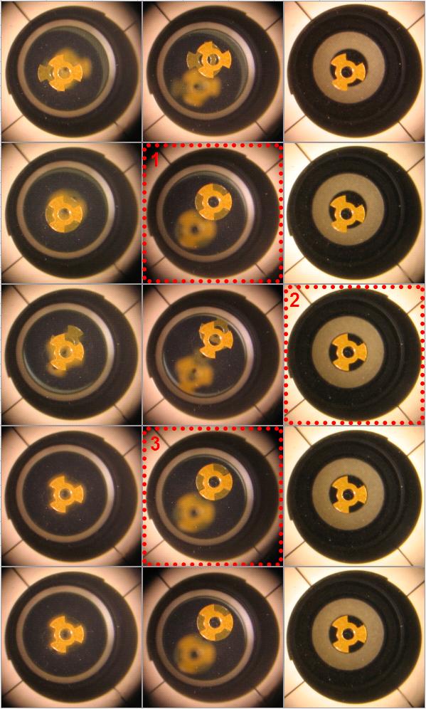
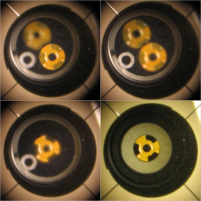
One problem I had to deal with is how to eliminate small CAM crescents under typical light illumination (no special light source clipped onto the spider-vanes.) Small CAM crescents are either undetectable or do not have enough clarity to figure out which primary knobs to move to eliminate them.
I did come up with a technique to do it but the technique is harder than using a cheshire – one of the negatives I listed about the CAM.

Photo#1 is the starting point (same as the case shown in the previous post). The goal is to eliminate the crescent as shown. I do assume each HotSpot tip points to one of the 3 primary knobs movements – as it should be.
Here are the steps:
1- I decollimate by twisting only primary knob “A” until the crescent becomes clearly visible as shown in photo#2
2- I make a mental note of knob “A” direction versus the axis of the crescent. My goal is the make both parallel. I can do this by twisting primary knob “C”. Photo#3 shows the result.
3- Since the crescent axis is now parallel to primary knob “A” movement, all I need to do is twist knob “A” until the crescent disappears as shown in photo#4
In summary, I decollimate with “A” then prep with “C” then finally eliminate the crescent with “A” again.
After 1 or 2 iterations between stacking P+2 via the secondary and the CAM using the above technique via the primary, precise collimation should be achieved under typical light illumination. As a final optional check, I decollimate one last time to ensure the final crescent axis is parallel to knob “A” direction and to ensure reflection 2 unstacking is symmetrical as shown within the cyan ovals

Photos shown in this post and the previous one used room light. I did achieve similar success using red light at night. Interestingly, by strategically pointing the red light held close to the edge of the OTA, I can illuminate only the CAM, only P+2, or both.

Jason
I did come up with a technique to do it but the technique is harder than using a cheshire – one of the negatives I listed about the CAM.
Photo#1 is the starting point (same as the case shown in the previous post). The goal is to eliminate the crescent as shown. I do assume each HotSpot tip points to one of the 3 primary knobs movements – as it should be.
Here are the steps:
1- I decollimate by twisting only primary knob “A” until the crescent becomes clearly visible as shown in photo#2
2- I make a mental note of knob “A” direction versus the axis of the crescent. My goal is the make both parallel. I can do this by twisting primary knob “C”. Photo#3 shows the result.
3- Since the crescent axis is now parallel to primary knob “A” movement, all I need to do is twist knob “A” until the crescent disappears as shown in photo#4
In summary, I decollimate with “A” then prep with “C” then finally eliminate the crescent with “A” again.
After 1 or 2 iterations between stacking P+2 via the secondary and the CAM using the above technique via the primary, precise collimation should be achieved under typical light illumination. As a final optional check, I decollimate one last time to ensure the final crescent axis is parallel to knob “A” direction and to ensure reflection 2 unstacking is symmetrical as shown within the cyan ovals
Photos shown in this post and the previous one used room light. I did achieve similar success using red light at night. Interestingly, by strategically pointing the red light held close to the edge of the OTA, I can illuminate only the CAM, only P+2, or both.
Jason
CNers have asked about a donation box for Cloudy Nights over the years, so here you go. Donation is not required by any means, so please enjoy your stay.

Recent Topics
-
-
Differences between eyepiece & 174mini
Newhobbies - May 12 2024 10:37 AM
Solar Observing and Imaging
-
 Northern Lights Livonia Michigan 5-10-24
EclipsingBinary - May 12 2024 10:30 AM
DSLR, Mirrorless & General-Purpose Digital Camera DSO Imaging
-
Solar Eclipse Photo
EclipsingBinary - May 12 2024 10:19 AM
DSLR, Mirrorless & General-Purpose Digital Camera DSO Imaging
-
-
44parts Sun mosaic (H-alpha) + AR3664 on May 11th, 2024
AstroTafelberg - May 12 2024 10:13 AM
Solar Observing and Imaging
-
 2 notable features at the terminator at 16% crescent: Rheita E and Burckhardt
CHnuschti - May 12 2024 10:02 AM
Lunar Observing and Imaging
-
-
-
Staying with the old or getting something new.
FCervini - May 12 2024 09:33 AM
Beginners Forum (No Astrophotography)


