17 inch spotplots
Started by
kfrederick
, Dec 21 2011 09:25 AM
107 replies to this topic
#1

kfrederick
-

-
topic starter
- Posts: 4,086
- Joined: 01 Feb 2008
Skylab
Posted 21 December 2011 - 09:25 AM
Here is the spotplots for a Mike Jones offaxis that I am building . I have had a 20offaxis for 2.5years and have thought this alot.Mikes design is as good as it gets .

#2
kfrederick
-
-
topic starter
- Posts: 4,086
- Joined: 01 Feb 2008
Skylab
Posted 21 December 2011 - 09:37 AM
A lot of advanages to this type of telescope .And more problems seting up the tilted optics .I wont to thank all who have helped so far .All opions are welcome
#3
dan_h
-
-

- Posts: 3,357
- Joined: 10 Dec 2007
Gemini
Posted 21 December 2011 - 10:38 AM
Thanks for posting. I hadn't realized just how good that design can be. How wide a field does the 0.5inch spot represent?
dan
dan
#4
George Kiger
-

-
- Posts: 121
- Joined: 19 May 2006
Vostok 1
Posted 21 December 2011 - 11:34 AM
Can you give us the details of the design?
#5
kfrederick
-
-
topic starter
- Posts: 4,086
- Joined: 01 Feb 2008
Skylab
Posted 21 December 2011 - 11:50 AM
The telescope uses a 17 inch primary mirror f8 .and a 4 inch convex secondary .And two correcting lens all surfaces are spherical except for the primary it is -1.4 conic .Mike is best to answer the spot plot question.KEVIN
#6
Mike I. Jones
-
-
- Posts: 5,023
- Joined: 02 Jul 2006
Fly Me to the Moon
Posted 21 December 2011 - 03:49 PM
Here's the OSLO-EDU file for Kevin's scope, with some help from David Ostwald on the coordinate translations and rotations. The spots look good anywhere over a 1" diameter FOV at focus, but I don't know how to make OSLO do multiple field points. I'll put up spots over the FOV in ZEMAX, where it's easy.
Mike
Mike
Attached Files
-
 4978053-Kev Frederick 17f8 Chief.len 1.16KB
137 downloads
4978053-Kev Frederick 17f8 Chief.len 1.16KB
137 downloads
#7
mark cowan
-
-
-

- Posts: 9,987
- Joined: 03 Jun 2005
Vendor (Veritas Optics)
Posted 21 December 2011 - 04:18 PM
Huge amount of awesomeness in this design. Could be why I'm building my own as well. 
And many many thanks to Kevin for keeping this ball rolling, people are simply not gonna believe what they're looking through - I think Mike said "17 inch apo!".
Best,
Mark
And many many thanks to Kevin for keeping this ball rolling, people are simply not gonna believe what they're looking through - I think Mike said "17 inch apo!".
Best,
Mark
#8
kfrederick
-
-
topic starter
- Posts: 4,086
- Joined: 01 Feb 2008
Skylab
Posted 21 December 2011 - 05:18 PM
Mike Jones work
Attached Thumbnails

#9
kfrederick
-
-
topic starter
- Posts: 4,086
- Joined: 01 Feb 2008
Skylab
Posted 21 December 2011 - 05:23 PM
More spot plots
Attached Thumbnails

#10
gatorengineer
-
-

- Posts: 3,204
- Joined: 28 Feb 2005
Gemini
Posted 21 December 2011 - 08:08 PM
Kevin,
How sensitive is it to exact spacing, and accuracy of the figure.... Some other OA designs go sideways quick with slight fabrication tolerances.
Mark
How sensitive is it to exact spacing, and accuracy of the figure.... Some other OA designs go sideways quick with slight fabrication tolerances.
Mark
#11
Mike I. Jones
-
-
- Posts: 5,023
- Joined: 02 Jul 2006
Fly Me to the Moon
Posted 21 December 2011 - 08:51 PM
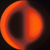
Here's the full-field spot diagram at 11 different field points, with the Airy disk shown at center. The outer circle is 30mm in diameter, and the spots and Airy disk are plotted within the circle 100X larger. As the OSLO file shows, I was able to get Kevin's design fairly well achromatized over the 0.45-0.66um spectral band, which brings indigo to near-violet light in focus as well as the usual blue-red color correction. If Kevin can make and assemble this scope as well as the design calls out, then Mark is right, the imagery should at least be semi-apochromatic in quality, and will be limited only by atmospheric turbulence conditions.
We must pay homage to Cuzzin Ed Jones here, as my design is based on his innovative Chief design. I deviated from Ed's BK7 glass choice to bring indigo and blue light in better control, and the fold mirror is convex rather than flat, but basically it's still a Chief.
I will work on tolerancing Kevin's Chief over the Christmas break and post up the results.
Mike
Attached Thumbnails

#12
kfrederick
-
-
topic starter
- Posts: 4,086
- Joined: 01 Feb 2008
Skylab
Posted 21 December 2011 - 08:57 PM
The primary was done by Carl Zambuto Mechanicaly holding the optics is like any other telescope they need in the correct spot The corector lens needs to be very close .If Mike gets the plots this good for a 17 inch f8 anything smaller would be perfect.So glad Mark Cowen is doing one lots of good ideas there.
#13
mark cowan
-
-
-
- Posts: 9,987
- Joined: 03 Jun 2005
Vendor (Veritas Optics)
Posted 22 December 2011 - 12:26 AM
At a -1.4 conic on the primary there's not a lot of difficulty at f/8. The lenses are going to be a bit pricey but definitely worthwhile. OTOH pretty much any EPs will work well. 
Best,
Mark
Best,
Mark
#14
kfrederick
-
-
topic starter
- Posts: 4,086
- Joined: 01 Feb 2008
Skylab
Posted 22 December 2011 - 06:18 AM
My plan is to Take the numbers off zemax and put them in a cnc mill and make a top piece that holds the focuser/ centrated corrector lens /secondary and the laser target.to atleast.010.On First setup move the ladder or primary so the moon focuses at the correct distance from the last lens .After that only use two bolts on the primary to adjust .The primary be able to move side to side as well. The top is fixed .That is the plan for now .The secondary is ground
#15
MKV
-
-
- Posts: 11,614
- Joined: 20 Jan 2011
Voyager 1
Posted 22 December 2011 - 07:31 AM
Half inch off axis for a 136 inch fl is 0.2 degrees. The 1 -inch field is 0.4 degrees - less than the Moon, which is between 0.48 and 0.57 degrees.Thanks for posting. I hadn't realized just how good that design can be. How wide a field does the 0.5inch spot represent?
dan
Mladen
#16
kfrederick
-
-
topic starter
- Posts: 4,086
- Joined: 01 Feb 2008
Skylab
Posted 22 December 2011 - 08:09 AM
The primary is f8 the telescope is f8.647 about 90x with my 40 mm.A offaxis can go as low a power as you wont and only lose apature the obstructed you go too low the %CO gets too big. Fun messing with this in Oslo .Good work by Dave O .Thanks for posting
#17
Mike I. Jones
-
-
- Posts: 5,023
- Joined: 02 Jul 2006
Fly Me to the Moon
Posted 22 December 2011 - 10:06 AM
Right, Mladen. As Kevin will almost exclusively use this as a visual instrument, there wasn't a need to design for a field wider than 1" diameter. It could be done, but at the expense of sharpness over the central 1" format. I have experimented with wider FOV's using a third element, but so far I have encountered diminishing returns. Ed's basic Chief design is hard to improve on! All I did here was bring a slightly wider spectral band under control. Kevin and I talked at length about the extra cost of the non-BK7 elements, and he wasn't the least bit concerned, so GOOD! Can't wait to hear about first light!
Mike
Mike
#18
Mike I. Jones
-
-
- Posts: 5,023
- Joined: 02 Jul 2006
Fly Me to the Moon
Posted 22 December 2011 - 10:14 AM
Three cheers on using CNC for this scope. The tolerancing work I did last night is pretty much demanding it. This is not a scope to make with hand tools and plywood. I actually used 0.01" for all decentrations in the tolerancing before having read your thread this morning, and that's actually at the hairy edge of acceptable. You'll still need to have some alignment adjustment on the decenter and tilt of the elements.
Not surprisingly, tilt of the convex secondary is the most sensitive parameter. It will definitely need precision tilt adjustment, and that must stay fixed over the full range of telescope elevation angles.
Tolerances take a while to adjust and execute. I'll try to finish and post up tolerances over the Christmas/NY break. What I've seen so far tells me that for both elements, radii should be held to 0.1% either side of nominal, thicknesses should be within ±0.005", and element wedge should be less than 0.001".
Mike
#19
kfrederick
-
-
topic starter
- Posts: 4,086
- Joined: 01 Feb 2008
Skylab
Posted 22 December 2011 - 11:30 AM
Great work Mike. How can you make a hyperbola primary and a spherical secondary combo to work? kf
#20
Mike I. Jones
-
-
- Posts: 5,023
- Joined: 02 Jul 2006
Fly Me to the Moon
Posted 22 December 2011 - 11:57 AM
In a centered system, it wouldn't work. But a Chief is not a centered system. It is a bizarre string of tilted, decentered elements, individually being figures of revolution, yet amazingly capable of phasing together to give a beautifully corrected broadband image over a small region. Like a Herrig multibounce, which is even weirder, it is hard to believe that a Chief can actually work, but as you know well Kevin, it does.
I for one am a strong believer that more of these "fringe-ey" non-intuitive wack-job telescope optical configurations still exist. They are all about delicate balancing of oblique high-order monochromatic and polychromatic aberrations over a finite "sweet spot" of sufficient optical quality. So those of you with any decent optical design program, keep on looking and experimenting. I don't think we've found them all.
Mike
#21
Mike I. Jones
-
-
- Posts: 5,023
- Joined: 02 Jul 2006
Fly Me to the Moon
Posted 22 December 2011 - 12:05 PM
Right Mark, it's not a challenging conic to make. Based on Kevin's project and our recent telephone conversation, Carl has already modified his analysis spreadsheet to enable him to properly figure mirrors with conic constants other than paraboloids. Knife edge shifts are simply multiplied by the conic constant, and Carl figures the mirror to have the scaled shifts between zones. A paraboloid has a conic constant of exactly -1. A hyperboloid with conic of -1.4 just means that the KE shifts for the equivalent paraboloid are scaled up by 1.4X. The same goes for Dall-Kirkham primaries, with conic constants ranging between zero and -1. This opens up a mirror maker's capabilities to Rosin, Ritchey-Chretien and Dall Kirkham primaries as well as traditional paraboloids.
Mike
Mike
#22
Benach
-
-
- Posts: 2,643
- Joined: 24 Jan 2008
Mercury-Atlas
Posted 22 December 2011 - 01:09 PM
Mike: To answer your request, I have worked a bit on ESA's COROT mission and the primary telescope is also a TMT with a correction system, so there you have another example of a weirdo scope.
#23
mark cowan
-
-
-
- Posts: 9,987
- Joined: 03 Jun 2005
Vendor (Veritas Optics)
Posted 22 December 2011 - 01:44 PM
What I've seen so far tells me that for both elements, radii should be held to 0.1% either side of nominal, thicknesses should be within ±0.005", and element wedge should be less than 0.001".
Is this absolute or can the spacings be adjusted to accommodate as-manuf actual specs? Both Kevin (I think) and myself are just planning to have these lenses made commercially.
My other question is (obviously) going to be about coatings - we've all seen the kind of charges for small qty coatings on lenses. With 4 surfaces what would any tradeoff look like?
Finally, since I'm already planning to manufacture large fast hyperboloids the quartz primary will be more like a vacation.
Best,
Mark
#24
MKV
-
-
- Posts: 11,614
- Joined: 20 Jan 2011
Voyager 1
Posted 22 December 2011 - 02:19 PM
Oh that goes without saying, Mike. Ed's configuration is awesome, even if the angular image field is somewhat restricted. It should be mentioned that its performance off axis is better than a classic paraboloid of the same aperture and focal length. Likewise, Ed's design is more compact than a classic Newtonian version.s Kevin will almost exclusively use this as a visual instrument, there wasn't a need to design for a field wider than 1" diameter. It could be done, but at the expense of sharpness over the central 1" format. I have experimented with wider FOV's using a third element, but so far I have encountered diminishing returns
The only thing I see as being somewhat more of a challenge is (1) the hyperboloidal primary, and (2) the fact that Ed's design is a compound system. As such it would have to be figured at the focus by autocollimation or interferometry. So, a lot more work than an ordinary Newotnian.
Mladen
#25
kfrederick
-
-
topic starter
- Posts: 4,086
- Joined: 01 Feb 2008
Skylab
Posted 22 December 2011 - 06:22 PM
Much thanks for the cool telescope .The best image I have seen was in my 20 f8 chief[ED Jones design] .Mark Harry is helping with testing of the secondary and lens .I have the best in the design and optics .The bigest problem is the perfect structure .Thanks to the "Jones" for this unreal unobstructed reflector design. It does work!
CNers have asked about a donation box for Cloudy Nights over the years, so here you go. Donation is not required by any means, so please enjoy your stay.

Recent Topics
-

-

-
-

-
Cannot reach focus of GSO 10" Truss RC with 0.8 reducer/corrector
p088gll - May 10 2024 06:06 PM
Cats & Casses
-
M81 and M82 (Bode's and Cigar Galaxies) Imaged May 7, 8, and 9.
KurtV - May 10 2024 05:56 PM
Experienced Deep Sky Imaging
-
 Suggestions for weekend targets? (8" Dobsonian)
MonogonMan - May 10 2024 05:51 PM
Beginners Forum (No Astrophotography)
-
AR3664. Canon EOS R7, RF200-800mm and RF Extender x1.4
Dennis_Oz - May 10 2024 05:40 PM
Solar Observing and Imaging
-

-