Any chance to try new control algorithms? Is there any way you could build the software to have several available to try out in an evening?
-Rich

Encoder-based PE Correction on the cheap
Started by
orlyandico
, Mar 25 2013 01:32 PM
328 replies to this topic
#177

orlyandico
-

-
topic starter
- Posts: 9,916
- Joined: 10 Aug 2009
Cosmos
Posted 14 April 2013 - 12:19 PM
I've hooked up the encoder to my AP600, which has a much more tractable periodic error. Still no resolution in sight.
If I could hook the encoder to the Mach1 and run the Mach1 with PEM enabled, I could characterize the encoder error very quickly. But alas the Mach1 polar scope bore does not rotate.
I tried measuring the PE with the CGEM while it was guiding, but the CGEM's PE is so bad that even when guiding I could only get 2" RMS
If it clears up during the week, I'll try guiding the AP600 (which from experience I know guides much, much better) and measure the residual PE. That should give me an idea of what sort of error the encoder and algorithm has.
#178
Mert
-
-

- Posts: 11,177
- Joined: 31 Aug 2005
Voyager 1
Posted 14 April 2013 - 02:23 PM
Hi Orlando,
Just for curiousity on how good your interpolator works,
would it be an idea to hookup the IBV660 just for a
comparison and see how the data looks?
I know your idea behind all this is an economical
solution for everybody
Just for curiousity on how good your interpolator works,
would it be an idea to hookup the IBV660 just for a
comparison and see how the data looks?
I know your idea behind all this is an economical
solution for everybody
#179
orlyandico
-
-
topic starter
- Posts: 9,916
- Joined: 10 Aug 2009
Cosmos
Posted 14 April 2013 - 10:35 PM
I have given thought to that Mert... maybe I'll do that when I've completely run out of ideas.
On the other hand... I'm beginning to suspect that the periodic error in the encoder is larger than 1 slot (i.e. 259.2 arc-seconds). In other words, the spacing between each of the 5000 slots is not perfectly consistent, because I'm seeing a very slow periodic error with a cycle of about 900 seconds. The IBV660B would not help with that since it solves the problem of interpolation between slots.
This actually makes sense because in its current state, the box smooths out small fast errors really well (much better than guiding) but does not correct long-term drift.
Things should be more clear when I measure the PE while guiding the AP600.
#180
Mert
-
-
- Posts: 11,177
- Joined: 31 Aug 2005
Voyager 1
Posted 15 April 2013 - 11:14 AM
I see Orlando, of course the precision of the encoder
is important, but what I was worried about is your post
on page 8 of this thread ( #5777368 ) where we see the
raw PE of the GEM leaking through!!!
I can't understand how can this happen, since these are
so to say "high" frequency errors, far out of the scope
of the "PE" of the encoder IMHO
Just my thoughts, hope to read more
#181
orlyandico
-
-
topic starter
- Posts: 9,916
- Joined: 10 Aug 2009
Cosmos
Posted 15 April 2013 - 11:21 AM
Those were due to dialing off the correction.
I have gotten a few thousand samples of data with active guiding on the AP600.
The RMS guiding was about 1" with a peak-to-peak of about 2 pixels or 6" (note guiding is on).
I found a consistent drift in the encoder data equivalent to about 1000ppm, which is completely attributable to the $%^%$#$!!#$#@ crystal resonator on the Arduino Mega 2560 I'm using now.
So I have two issues now:
1) try to replace the ceramic resonator on the Mega 2560 with a 50ppm or 25ppm crystal
2) I need to characterize the periodic error of the algorithm and encoder, trying to figure out the FFTs in Excel
#182
vdb
-

-

- Posts: 1,618
- Joined: 08 Dec 2009
Surveyor 1
Posted 15 April 2013 - 11:27 AM
So maybe the TDM encoders have a PE table definition per unit, maybe they run a calibration against an encoder ... but that seems very unlikely ... how could they sync to that table.
#183
orlyandico
-
-
topic starter
- Posts: 9,916
- Joined: 10 Aug 2009
Cosmos
Posted 15 April 2013 - 11:54 AM
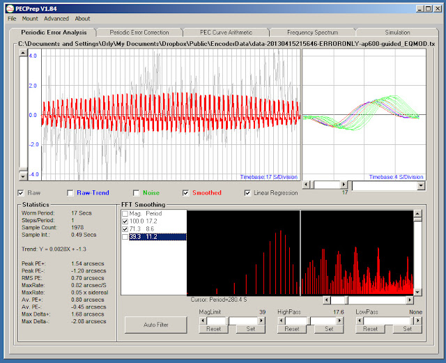
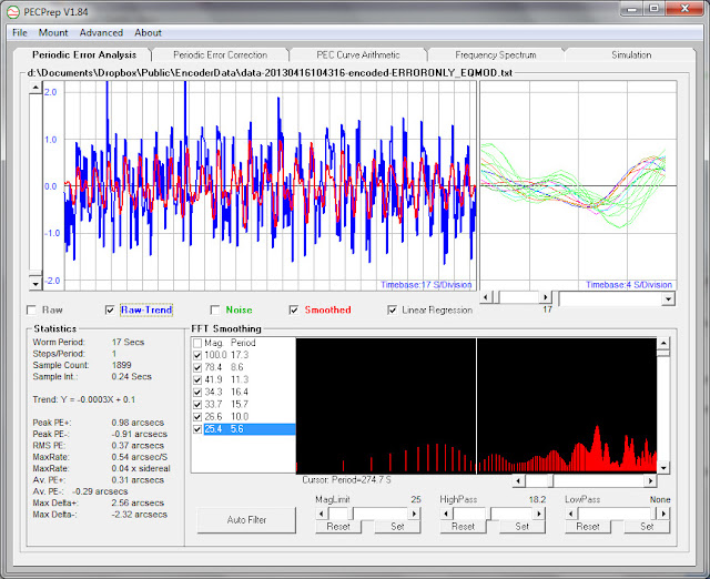
Ok so I imported the guided encoder data from the AP600 into PECPrep, which was quite easy.. too bad I had already done the FFT analysis in Excel. But PECPrep makes things much easier.
The average PE (guided) according to both PECPrep and PHD was about 1" and the peak-to-peak (according to PECPrep) was about 7". This corresponds well with what I saw on the PHD graph (peaks about 2 pixels p-p at 3.05"/pixel).

PECPrep identified harmonics are
11.3 = gear harmonic (40X)
22.5 = gear harmonic (20X)
222.1 = gear harmonic (2X)
74.4 = gear harmonic (6X)
44.6 = gear harmonic (10X)
114.7 = gear harmonic (4X)
446.7 = worm fundamental
8.6 = encoder harmonic (2X)
17.2 = encoder fundamental
167.2 = probable encoder sub-harmonic (1/10)
Most of the noise is from the Nippon Pulse 150:1 gearbox in the AP600. The fundamental is also quite strongly detected by the encoder, in spite of the guiding being active.

When I remove all the known terms leaving only the encoder terms the total PE is about 2.7" p-p. This is solely due to the encoder interpolation algorithm. The 17.2 second (encoder slot harmonic) is the strongest overall though.
The average PE (guided) according to both PECPrep and PHD was about 1" and the peak-to-peak (according to PECPrep) was about 7". This corresponds well with what I saw on the PHD graph (peaks about 2 pixels p-p at 3.05"/pixel).
PECPrep identified harmonics are
11.3 = gear harmonic (40X)
22.5 = gear harmonic (20X)
222.1 = gear harmonic (2X)
74.4 = gear harmonic (6X)
44.6 = gear harmonic (10X)
114.7 = gear harmonic (4X)
446.7 = worm fundamental
8.6 = encoder harmonic (2X)
17.2 = encoder fundamental
167.2 = probable encoder sub-harmonic (1/10)
Most of the noise is from the Nippon Pulse 150:1 gearbox in the AP600. The fundamental is also quite strongly detected by the encoder, in spite of the guiding being active.
When I remove all the known terms leaving only the encoder terms the total PE is about 2.7" p-p. This is solely due to the encoder interpolation algorithm. The 17.2 second (encoder slot harmonic) is the strongest overall though.
#184
Starhawk
-
-

- Posts: 6,634
- Joined: 16 Sep 2008
Space Ranger
Posted 15 April 2013 - 03:20 PM
I was thinking- you could put the encoder on top of the Mach 1 hub and use a shaft going through the axis to mount through. It's a sort of inverse setup, but it could give the data you are looking for.
-Rich
-Rich
#185
orlyandico
-
-
topic starter
- Posts: 9,916
- Joined: 10 Aug 2009
Cosmos
Posted 15 April 2013 - 03:26 PM
I'm beginning to suspect that guiding etc. is not needed at all.
The encoder is obviously picking up good data, subject to its own 2.7" periodic error. Even with the huge fundamental present (when not guiding) PECPrep would be able to filter that out.
I'll collect more data with no guiding (just running the mount blind) to validate.
And as for the errors in the ceramic resonator.. I have a solution but it will take some time. An older (and cheaper) board - the Arduino Mega 1280 - uses a crystal. These are $26 a pop. Have to wait for them to ship from China.
I can't use the smaller Arduino (Duemilanove) which is $15 because it doesn't have enough pins to support the ST-4 input and output.
Now that I've quantified the errors, I think I am close to the end. Once this works, the next hurdle will be productizing it, or at least making it as easy to build as possible.
#186
Mert
-
-
- Posts: 11,177
- Joined: 31 Aug 2005
Voyager 1
Posted 15 April 2013 - 03:55 PM
Just a minor question on the crystal Orlando:
why don't you use a seperate little board with it's
own crystal to clock the ADC-chip and sync to clock the
data into the Arduino? Wouldn't that be possible to do?
Just use a counter to count for the ADC cycle and then
trigger a signal that makes the Arduino read out the data?
Or if not, why not use a paralel data out chip with external
crystal, like the Maxim-flashADC-1114 chip ( 150Msps ),
or TI-16bit-ADC-ads1209.
I don't know how stable the clock of the Arduino is but
very likely as you stated, this is a big cause of in-
stability.
Just a couple of thoughts FWIW :-)
#187
Mert
-
-
- Posts: 11,177
- Joined: 31 Aug 2005
Voyager 1
Posted 15 April 2013 - 04:10 PM
Likely you already saw this from schematic.pdf on
the internet?
Seems to be easy to cut the clock existent on the pcb
and add your own.
the internet?
Seems to be easy to cut the clock existent on the pcb
and add your own.
Attached Thumbnails

#188
orlyandico
-
-
topic starter
- Posts: 9,916
- Joined: 10 Aug 2009
Cosmos
Posted 15 April 2013 - 06:22 PM
Hi Mert,
Yup am familiar with the circuit. Easy to do the mod on an Arduino Uno R3, but not so easy on an Mega 2560 due to the surface-mount CPU and crystal.
Anyway I have already bought a couple of Mega 1280 clones. These have real crystals, and I also have some high-grade 16 MHz crystals on hand if the ones on the boards aren't good enough.
I also thought about using a separate clock reference, daughter board that produces a precise clock and interrupts the Arduino. There is a $35 GPS board that produces a 10Hz signal. That is extremely accurate (GPS disciplined). But at the end of the day all these solutions add complexity. It's better to just use a Mega 1280 and be done with it.
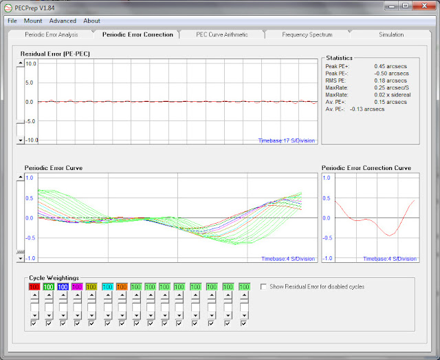
Did some more processing of the encoder data. With the worm period set to 17.25 seconds:
Note that 1978 samples were used, which covers about 56 encoder slots. There is a slight precession of the curve, but it can't be helped (no indexing here!)
And the periodic error correction curve. There is a residual PE of about 1.6" which cannot be removed by this PEC curve... is this coincidence? (the TDM reports similar range of corrected performance)
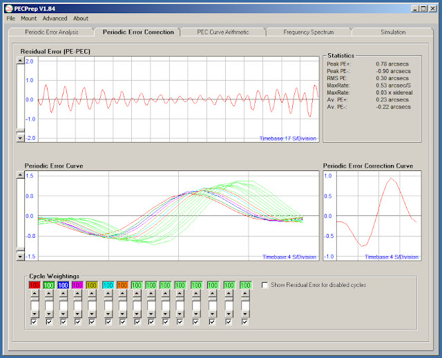
PECPrep produced a 17-slot (1 entry/second) PEC curve covering the 17.25-second encoder period, which I can just plug into my program. Probably don't even need interpolation or anything.
Will report when I've added this code.
Yup am familiar with the circuit. Easy to do the mod on an Arduino Uno R3, but not so easy on an Mega 2560 due to the surface-mount CPU and crystal.
Anyway I have already bought a couple of Mega 1280 clones. These have real crystals, and I also have some high-grade 16 MHz crystals on hand if the ones on the boards aren't good enough.
I also thought about using a separate clock reference, daughter board that produces a precise clock and interrupts the Arduino. There is a $35 GPS board that produces a 10Hz signal. That is extremely accurate (GPS disciplined). But at the end of the day all these solutions add complexity. It's better to just use a Mega 1280 and be done with it.
Did some more processing of the encoder data. With the worm period set to 17.25 seconds:
Note that 1978 samples were used, which covers about 56 encoder slots. There is a slight precession of the curve, but it can't be helped (no indexing here!)
And the periodic error correction curve. There is a residual PE of about 1.6" which cannot be removed by this PEC curve... is this coincidence? (the TDM reports similar range of corrected performance)
PECPrep produced a 17-slot (1 entry/second) PEC curve covering the 17.25-second encoder period, which I can just plug into my program. Probably don't even need interpolation or anything.
Will report when I've added this code.
#189
orlyandico
-
-
topic starter
- Posts: 9,916
- Joined: 10 Aug 2009
Cosmos
Posted 16 April 2013 - 08:46 AM
Here's the data from the encoder and AP600 with no guiding or corrections:
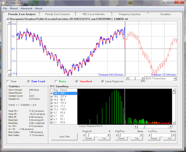
The periodic error due to the encoder 17.2s and 8.6s harmonics is about 3.7" here
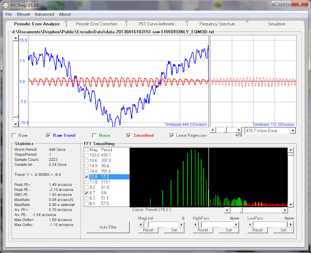
With correction turned on (the Arduino pushing ST-4 pulses to the AP 9000 QMD drive) - total PE with all components is about 2" p-p and RMS PE is 0.37"
Periodic error due to the 17.2s and 8.6s components (note it's smaller due to the 17-slot PEC I've applied to the interpolator)
Compared to before the PEC:
So it does look like "interpolation PEC" does work to a certain extent and reduces the periodic error of the interpolation algorithm from about 2.7" to about 1.5" - not a lot but the encoder PE limits the resolution of the whole system. Without the PEC the encoder cannot discriminate anything below 2.7" because of its own error, if that error is reduced to 1.5" then a bit more accuracy can be extracted.
Now all I need is a decent crystal-clocked Arduino board to solve the long-term drift problem... (and some clear skies to verify performance).
The periodic error due to the encoder 17.2s and 8.6s harmonics is about 3.7" here
With correction turned on (the Arduino pushing ST-4 pulses to the AP 9000 QMD drive) - total PE with all components is about 2" p-p and RMS PE is 0.37"
Periodic error due to the 17.2s and 8.6s components (note it's smaller due to the 17-slot PEC I've applied to the interpolator)
Compared to before the PEC:
So it does look like "interpolation PEC" does work to a certain extent and reduces the periodic error of the interpolation algorithm from about 2.7" to about 1.5" - not a lot but the encoder PE limits the resolution of the whole system. Without the PEC the encoder cannot discriminate anything below 2.7" because of its own error, if that error is reduced to 1.5" then a bit more accuracy can be extracted.
Now all I need is a decent crystal-clocked Arduino board to solve the long-term drift problem... (and some clear skies to verify performance).
#190
Mert
-
-
- Posts: 11,177
- Joined: 31 Aug 2005
Voyager 1
Posted 17 April 2013 - 02:51 PM
Hi Orlando,
I don't quit understand the "phase shifting" in the signal
in the PECPrep window.
What signal is analized is this? ( from the encoder, or
from a star through a webcam, so the mounts signal? )
Just saw a new Arduino board: Arduino Due 84 MHz and 12 bit ADC
Seems to be able to do 50K samples per second!
#191
Starhawk
-
-
- Posts: 6,634
- Joined: 16 Sep 2008
Space Ranger
Posted 17 April 2013 - 05:23 PM
OK, if you can get to operating at 1.6" PE, then the following performance would be practical for half-pixel error:
Pixel size Focal Length Max
10 micron 1289.16 mm
9 micron 1160.24 mm
8 micron 1031.32 mm
7 micron 902.41 mm
6 micron 773.49 mm
5 micron 644.58 mm
4 micron 515.66 mm
Note this is for indefinite exposure. Not bad performance, already.
-Rich
Pixel size Focal Length Max
10 micron 1289.16 mm
9 micron 1160.24 mm
8 micron 1031.32 mm
7 micron 902.41 mm
6 micron 773.49 mm
5 micron 644.58 mm
4 micron 515.66 mm
Note this is for indefinite exposure. Not bad performance, already.
-Rich
#192
orlyandico
-
-
topic starter
- Posts: 9,916
- Joined: 10 Aug 2009
Cosmos
Posted 17 April 2013 - 07:28 PM
Bad news... I just discovered after extensive testing that the Arduino's sense of time is wrong. The internal timer routines actually lose ticks (when compared to timestamping from my laptop) over time. I thought this was due to the inaccurate ceramic resonator, but I get the same behavior with my 80MHz Max32 which I've verifed has a pretty good crystal.
I believe the loss of time is due to either the SPI routine that talks to the ADC, the arctangent calculation, or the serial routine talking to the PC itself.
Anyway the drift induced by the lost time is much greater than any interpolation errors, so I have to fix this first. This completely explains why as it is the box can smooth out small sharp errors, but induces a long-term drift even over one worm cycle. Need to add an external time reference, am thinking of a Chronodot or DS1390.
Mert, I have looked at the Due. It won't work for this project because its ADC inputs are not differential, and the input span is only 3.3V because the Due is a 3.3V part.
#193
AndreyYa
-
-
- Posts: 138
- Joined: 05 Dec 2006
Vostok 1
Posted 17 April 2013 - 07:50 PM
Hi Orlando,
first thank you for interesting topic. I had some similar ideas, and I happy to see them implemented.
Regarding loosing timer tics: maybe arranging timer counting in timer interrupt manner could help. Usually it helps to make more or less safe processing of such kind of tasks. Does Arduino allow to make timer interrupt unmasked, or increase timer interrupt priority?
#194
orlyandico
-
-
topic starter
- Posts: 9,916
- Joined: 10 Aug 2009
Cosmos
Posted 17 April 2013 - 08:47 PM
Andrey, the Arduino implements the timer using an interrupt.
I am using the built-in millis() function.
I also tried to set up my own timekeeping routine by installing my own ISR. It still loses ticks.
Anyway I have already ordered the PCF8583 RTC. 1/100 second resolution, through-hole DIP8 package so easy to use (unlike the Dallas DS1390 which is an SMD part).
#195
AndreyYa
-
-
- Posts: 138
- Joined: 05 Dec 2006
Vostok 1
Posted 17 April 2013 - 10:10 PM
I see, thank you Orlando.
It looks a bit strange... maybe some more high priority interrupts prevent it, like serial port handling.
It looks a bit strange... maybe some more high priority interrupts prevent it, like serial port handling.
Andrey, the Arduino implements the timer using an interrupt.
I am using the built-in millis() function.
I also tried to set up my own timekeeping routine by installing my own ISR. It still loses ticks.
Anyway I have already ordered the PCF8583 RTC. 1/100 second resolution, through-hole DIP8 package so easy to use (unlike the Dallas DS1390 which is an SMD part).
#196
rpineau
-
-

- Posts: 483
- Joined: 30 May 2012
Messenger
Posted 17 April 2013 - 11:09 PM
It depends on the timer. I personally use an ATMega32U4 for some stuff and only timer 0 and 1 have a higher priority than the USART1 (and in my case a lower priority than any external interrupt as well as the usb interrupt).
For me it goes (from highest to lowest priority) :
External interrupts, USB, WDT, Timer 1, Timer 0, SPI, USUART, ...
So I assume Orly already checked this and is using the timer with the highest priority for the AVR he's using.
In the case of the ATMega 1280/2560 the highest priority timer is Timer 2 and it has a higher priority than the SPI and USART0 .
Regards, Rodolphe
#197
orlyandico
-
-
topic starter
- Posts: 9,916
- Joined: 10 Aug 2009
Cosmos
Posted 17 April 2013 - 11:41 PM
Thanks Rodolphe.
I may look at Timer 2. But what you are saying is that external interrupts and USB have the highest priority of all? so it should be possible for me to use an external clock generator for timing.. I thought an external interrupt and an internal timer interrupt were more or less the same thing..
I may look at Timer 2. But what you are saying is that external interrupts and USB have the highest priority of all? so it should be possible for me to use an external clock generator for timing.. I thought an external interrupt and an internal timer interrupt were more or less the same thing..
#198
rpineau
-
-
- Posts: 483
- Joined: 30 May 2012
Messenger
Posted 18 April 2013 - 01:24 AM
Each interrupt source has a priority. External interrupt INT0 for example has the highest priority IF 2 interrupt are triggered at the same time. Also when an interrupt is triggered, all other interrupt are disabled.
You can see the priority on page 105 of the manual : http://www.atmel.com...ges/doc2549.pdf
Also found on page 18 :
"The lowest addresses in the program memory space are by default defined as the Reset and Interrupt Vectors. The complete list of vectors is shown in “Interrupts” on page 105. The list also determines the priority levels of the different interrupts. The lower the address the higher is the priority level. "
There is more explanation about how interrupt are handled on that same page of the manual (page 18 that is).
As to the use of external interrupt, if you use the PCF8583 RTC INT* output and wire it to INT0 you should get something very stable in term of time tracking. You might need to take the interrupt response time in account (5 clock cycle minimum, see page 20 of the manual).
Regards, Rodolphe
#199
orlyandico
-
-
topic starter
- Posts: 9,916
- Joined: 10 Aug 2009
Cosmos
Posted 18 April 2013 - 02:01 AM
Hi Rodolphe,
I have a long thread on this timekeeping topic here - http://arduino.cc/fo...index.php/topic,160899.0.html
Since INT0 is on pin 2, I should be able to use it without issue right? I once put an interrupt on pin 1 or 0... Serial.print sure screwed up my DSC!
I have a long thread on this timekeeping topic here - http://arduino.cc/fo...index.php/topic,160899.0.html
Since INT0 is on pin 2, I should be able to use it without issue right? I once put an interrupt on pin 1 or 0... Serial.print sure screwed up my DSC!
#200
orlyandico
-
-
topic starter
- Posts: 9,916
- Joined: 10 Aug 2009
Cosmos
Posted 18 April 2013 - 03:30 AM
Unrelated: Just received my $25 Womarts.com 320x240 color TFT LCD resistive touch screen shield 
In one fell swoop I solve the problem of how to provide input to the controller. I can make a very nice UI for it, have real-time graphing of periodic error, etc. etc. etc.
Now if only I could get the core functionality working reliably...
In one fell swoop I solve the problem of how to provide input to the controller. I can make a very nice UI for it, have real-time graphing of periodic error, etc. etc. etc.
Now if only I could get the core functionality working reliably...
CNers have asked about a donation box for Cloudy Nights over the years, so here you go. Donation is not required by any means, so please enjoy your stay.

Recent Topics
-

-
-

-

-
-

-
 Quick pics of today's Sun minutes before clouds rolled in
Hitech - Today, 11:01 PM
Solar Observing and Imaging
-
The one night that was clear after weeks of ran, this happens
chvvkumar - Today, 10:53 PM
Beginning Deep Sky Imaging
-
 Fire in the sky
piaras - Today, 10:49 PM
DSLR, Mirrorless & General-Purpose Digital Camera DSO Imaging
-