Here's a basic question- Why is your mount not black?
That's good news on the installation fix.
-Rich

Encoder-based PE Correction on the cheap
Started by
orlyandico
, Mar 25 2013 01:32 PM
328 replies to this topic
#277

Mert
-

-

- Posts: 11,179
- Joined: 31 Aug 2005
Voyager 1
Posted 25 June 2013 - 01:40 PM
I didn't know that about the fires 
so yes, you are right, keep breathing well!
so yes, you are right, keep breathing well!
#278
orlyandico
-
-
topic starter
- Posts: 9,916
- Joined: 10 Aug 2009
Cosmos
Posted 27 June 2013 - 01:47 PM
Update. The haze has lifted temporarily, and I have been able to acquire some (actually a lot of) guiding data.
Good news: the random large errors are gone.
Bad news: the constant drift is still there. This must be the encoder concentricity/swash problem. This can be solved by adding a low-tic absolute encoder (which I already have) to index the PE of the main encoder. Or.. more elegant (and more expensive).. use an absolute encoder and calibrate it once by rotating the mount 360 degrees.
The problem with correcting the PE of the main encoder is, if there is some change in the concentricity of the shaft, the PE will change requiring another calibration.
The only way to (a) lessen the long slow PE; and (b) suppress variations which would force recalibration - is a very robust mechanical encoder mount. It is now clear to me that any shaft-mounted encoder is going to be hostage to mounting tolerances, and no amount of code or signal conditioning can fix that.
I am sick and tired of this approach. Having new encoder housings machined (to replace my wooden thing) would cost me another chunk of change.
I have decided to eat my pride and take the project in a different direction.
Currently you can buy Renishaw LM10 magnetic linear encoders on ebay for $80 a pop. These do the interpolation internally and have 1 micrometer resolution.
The tape is dirt-cheap, $20 for a 300mm length (which is enough for one mount). They will give about 200K to 300K tics for a half-rotation (180 degrees).
Based on the diameter of my RA housing (around which I will wrap the tape) the accuracy of the system is only 3" per tick. But - it is resilient to mounting inaccuracy. The SiTech guys are already using this design successfully.
The cost of tape and the read head is less than it would cost me to have a new encoder housing machined. One potential deal-breaker, the SDE (interpolation error) is as much as 40" peak-to-peak. But repeatability is under 1 tic as long as moving in one direction (which an RA axis does).
Anyway, now for another 2-week wait for the parts.. I will have to throw away all the code I wrote for robustly reading the ADC, doing sine-cosine interpolation, etc. etc. because the Renishaw read head has a digital output.
The good side is... these LM10 magnetic read heads and their corresponding tape are a new low in lows in pricing. I actually have a Heidenhain LIDA and Renishaw RGH optical read head lying around, but the (optical) tape is darn expensive and I can never find any...
So any of you folks who are curious about encoder interpolation, run, don't walk, to ebay and buy the LM10 read head ($80) and tape ($20). I don't know how long they'll last at these prices.
Worst-case, I can't get it to work and you wasted $100. But it's only $100 (as compared to the $400-plus for a rotary encoder).
Good news: the random large errors are gone.
Bad news: the constant drift is still there. This must be the encoder concentricity/swash problem. This can be solved by adding a low-tic absolute encoder (which I already have) to index the PE of the main encoder. Or.. more elegant (and more expensive).. use an absolute encoder and calibrate it once by rotating the mount 360 degrees.
The problem with correcting the PE of the main encoder is, if there is some change in the concentricity of the shaft, the PE will change
requiring another calibration.
The only way to (a) lessen the long slow PE; and (b) suppress variations which would force recalibration - is a very robust mechanical encoder mount. It is now clear to me that any shaft-mounted encoder is going to be hostage to mounting tolerances, and no amount of code or signal conditioning can fix that.
I am sick and tired of this approach. Having new encoder housings machined (to replace my wooden thing) would cost me another chunk of change.
I have decided to eat my pride and take the project in a different direction.
Currently you can buy Renishaw LM10 magnetic linear encoders on ebay for $80 a pop. These do the interpolation internally and have 1 micrometer resolution.
The tape is dirt-cheap, $20 for a 300mm length (which is enough for one mount). They will give about 200K to 300K tics for a half-rotation (180 degrees).
Based on the diameter of my RA housing (around which I will wrap the tape) the accuracy of the system is only 3" per tick. But - it is resilient to mounting inaccuracy. The SiTech guys are already using this design successfully.
The cost of tape and the read head is less than it would cost me to have a new encoder housing machined. One potential deal-breaker, the SDE (interpolation error) is as much as 40" peak-to-peak. But repeatability is under 1 tic as long as moving in one direction (which an RA axis does).
Anyway, now for another 2-week wait for the parts.. I will have to throw away all the code I wrote for robustly reading the ADC, doing sine-cosine interpolation, etc. etc. because the Renishaw read head has a digital output.
The good side is... these LM10 magnetic read heads and their corresponding tape are a new low in lows in pricing. I actually have a Heidenhain LIDA and Renishaw RGH optical read head lying around, but the (optical) tape is darn expensive and I can never find any...
So any of you folks who are curious about encoder interpolation, run, don't walk, to ebay and buy the LM10 read head ($80) and tape ($20). I don't know how long they'll last at these prices.
Worst-case, I can't get it to work and you wasted $100. But it's only $100 (as compared to the $400-plus for a rotary encoder).
#279
Starhawk
-
-

- Posts: 6,634
- Joined: 16 Sep 2008
Space Ranger
Posted 27 June 2013 - 03:34 PM
What are you going to mount the tape on?
-Rich
-Rich
#280
orlyandico
-
-
topic starter
- Posts: 9,916
- Joined: 10 Aug 2009
Cosmos
Posted 27 June 2013 - 10:27 PM
the RA axis on the AP600 has a nice circular area right next to the worm. I can attach the self-adhesive tape to this area. The challenge is how to mount the read head.
If this works out I'll see about where to put tape on the CGEM (which arguably would benefit more from such a device).
If this works out I'll see about where to put tape on the CGEM (which arguably would benefit more from such a device).
#281
Per Frejvall
-
-

-

- Posts: 893
- Joined: 28 Sep 2012
In Memoriam
Posted 28 June 2013 - 01:07 AM
Your findings verify what I have heard from people who design this stuff: mounting the encoders is a very sensitive matter. They need to be so totally centered or you get periodic shifts around the revolution. This only emphasizes how extremely hard it is to retrofit encoders to a mount.
I am impressed by your persistance and the fact that you are breaking ground here for the rest of us do-it-yourselfers, and, on top of that, supplies insight into how feasable a "bolt-on" encoder solution actually is.
Can't wait for the update!
/per
I am impressed by your persistance and the fact that you are breaking ground here for the rest of us do-it-yourselfers, and, on top of that, supplies insight into how feasable a "bolt-on" encoder solution actually is.
Can't wait for the update!
/per
#282
orlyandico
-
-
topic starter
- Posts: 9,916
- Joined: 10 Aug 2009
Cosmos
Posted 28 June 2013 - 01:53 AM
Per, the challenge is to build the encoder add-on and make it (relatively) insensitive to mechanical or manufacturing tolerances.
The best solution is to use two read heads 180 degrees apart - the error due to concentricity gets canceled out if you average the readings. The easiest way to do this is to purchase two Renishaw read heads and a REXM ring. The rings are quite expensive though. I believe this is the technology used by AP. Not sure what encoder lurks inside 10Micron mounts though.
The LM10 and its corresponding magnetic tape seems to be the cheapest solution. The resolution is low, 3" per tic. However I think it can be used: the Gurley and Heidenhain 5000-ppr encoders used in the SiTech and TDM respectively, both only have a repeatable accuracy of +/- 10" and yet manage sub-arcsecond tracking.
#283
Per Frejvall
-
-
-
- Posts: 893
- Joined: 28 Sep 2012
In Memoriam
Posted 29 June 2013 - 12:49 AM
Yes, that would be one way to handle one error. Even better would be to mount them "reasonably good enough" and model them at the factory. This is what 10Micron does and it turns a good encoding solution into an even better one. This is interesting technology indeed!
/per
/per
#284
orlyandico
-
-
topic starter
- Posts: 9,916
- Joined: 10 Aug 2009
Cosmos
Posted 29 June 2013 - 01:03 AM
Ahh.. well "modeling at the factory" is the obvious solution. My friend who works with IC fabrication equipment says that when they install the machinery on-site, they have to calibrate/model the encoders in situ (can't do at factory because the machinery shifts during transport - of course this is a multi-ton IC lithography machine, not a mount which is much lighter).
This scheme wouldn't work for aftermarket add-ons though. I have been looking at the TDM and as far as I can see they have solved this problem by:
1) using a steel shaft
2) a very sturdy encoder housing/bracket
3) the encoder that they use has two compression rings, on opposite ends of the encoder; this would help to center the encoder shaft and reduce concentricity errors.
but.. as I mentioned on the SciTech group, these shaft-type encoders are fundamentally limited by the small code wheel. So to get true sub-arcsecond pointing and tracking, you need a large ring - which is what AP has been doing.
#285
famax
-

-

- Posts: 255
- Joined: 01 Jul 2007
Mariner 2
Posted 29 June 2013 - 01:03 PM
Per, your information about how 10µ manage the encoders is based on a guess ?
We can see on their website that performances are based on an external encoder measurment, that leads to think that error calibration are managed the way you describe.
By the way it is easy to find desciption of an encoder system IP claimed by 10µ and baader on the web.
THe question is to know if 10µ actually used this encoder design or if they use third party one.
#286
Per Frejvall
-
-
-
- Posts: 893
- Joined: 28 Sep 2012
In Memoriam
Posted 30 June 2013 - 09:35 AM
Famax,
My information regarding the encoder solution is from the horses mouth and thus initiated. Could you please point me to the IP discussion as I cannot find it? There shouldn't be a third party solution in there as far as I can tell.
/per
My information regarding the encoder solution is from the horses mouth and thus initiated. Could you please point me to the IP discussion as I cannot find it? There shouldn't be a third party solution in there as far as I can tell.
/per
#287
Starhawk
-
-
- Posts: 6,634
- Joined: 16 Sep 2008
Space Ranger
Posted 30 June 2013 - 10:09 AM
Just a question- anything which is a real variance in a CGEM drive has a cycle time of 10 minutes or 2.4 minutes for either the worm or the motor gear heads. It should be possible to have the controller ignore anything slower than that, and even zero itself based on it so whatever the swash was, it wouldn't show up in the guidance corrections from the encoder.
-Rich
-Rich
#288
orlyandico
-
-
topic starter
- Posts: 9,916
- Joined: 10 Aug 2009
Cosmos
Posted 23 July 2013 - 07:58 AM
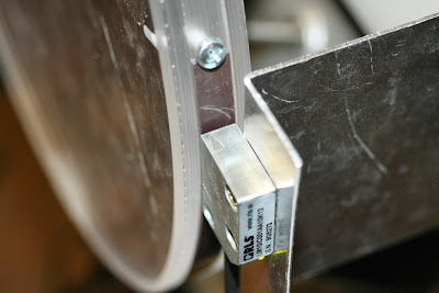
I finally got my Renishaw LM10IC and the Bogen 2mm magnetic tape.
Here's the tape attached to the RA housing of my AP600. The tape cost about $35 (including shipping) for a 300mm length. This was a little bit more than necessary. The tape is self-adhesive but has a steel backing, I had a heck of a time cutting it; had to use a dremel cutoff wheel and managed to ding the magnetic material in the process, so there might be problems there.
Unfortunately mounts such as the CGEM don't have a large round area to apply the tape; these types of mounts would require a large wheel that screws into the polar scope bore.
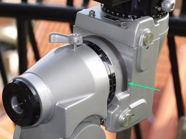
I still haven't figured out how to attach the encoder read head itself, will think about that this weekend..
Here's the tape attached to the RA housing of my AP600. The tape cost about $35 (including shipping) for a 300mm length. This was a little bit more than necessary. The tape is self-adhesive but has a steel backing, I had a heck of a time cutting it; had to use a dremel cutoff wheel and managed to ding the magnetic material in the process, so there might be problems there.
Unfortunately mounts such as the CGEM don't have a large round area to apply the tape; these types of mounts would require a large wheel that screws into the polar scope bore.
I still haven't figured out how to attach the encoder read head itself, will think about that this weekend..
#289
orlyandico
-
-
topic starter
- Posts: 9,916
- Joined: 10 Aug 2009
Cosmos
Posted 02 October 2013 - 06:12 PM
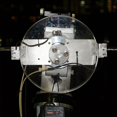
I had a new encoder wheel of 300mm diameter machined.
Currently I am using a single Renishaw RLS LM10IC read head, this gives about 900k ticks per revolution, or 1.4 arc-seconds per tick.
The problem here is that the LM10IC has a sub-divisional error of +/- 3.5um, or about +/- 5". Hence unless this SDE can be tamed, the system will be accurate to no more than +/- 5" which is terrible.
I used such a large wheel, which is impractical for most people, because I wanted to increase the accuracy - a smaller wheel would have less ticks per arc-second, and thus a bigger SDE.
Granted this is an extremely primitive solution (check out that chopping board!)

but I'm waiting for a properly machined encoder mount. I'll also add another read head to cancel out odd harmonics and hopefully reduce the SDE by a factor of two. If the phase shift between the two encoders is exactly 180 degrees, that would actually completely cancel out the SDE...
Currently this is the measured error with the LM10

The small sharp excursions are due to the SDE (the above graph is 5 worm cycles, there also is a large-scale error due to eccentricity which the 2nd encoder will fix)
Currently I am using a single Renishaw RLS LM10IC read head, this gives about 900k ticks per revolution, or 1.4 arc-seconds per tick.
The problem here is that the LM10IC has a sub-divisional error of +/- 3.5um, or about +/- 5". Hence unless this SDE can be tamed, the system will be accurate to no more than +/- 5" which is terrible.
I used such a large wheel, which is impractical for most people, because I wanted to increase the accuracy - a smaller wheel would have less ticks per arc-second, and thus a bigger SDE.
Granted this is an extremely primitive solution (check out that chopping board!)
but I'm waiting for a properly machined encoder mount. I'll also add another read head to cancel out odd harmonics and hopefully reduce the SDE by a factor of two. If the phase shift between the two encoders is exactly 180 degrees, that would actually completely cancel out the SDE...
Currently this is the measured error with the LM10
The small sharp excursions are due to the SDE (the above graph is 5 worm cycles, there also is a large-scale error due to eccentricity which the 2nd encoder will fix)
#290
Starhawk
-
-
- Posts: 6,634
- Joined: 16 Sep 2008
Space Ranger
Posted 02 October 2013 - 07:39 PM
The CGEm actually does have a nice circular section to make and encoder on- look carefully at what moves with the head.
-Rich
-Rich
#291
orlyandico
-
-
topic starter
- Posts: 9,916
- Joined: 10 Aug 2009
Cosmos
Posted 29 October 2013 - 11:55 PM
I have solved the gross mis-alignment and error drift by using two RLS magnetic read heads. These read heads have the virtue of being cheap on ebay ($80 a pop, I managed to get two for $60 using Best Offer). and there are hundreds of them on sale on ebay.. supposedly from a solar cell factory gone bust.
I also used a huge acrylic encoder wheel (thanks Josh!) with the magnetic tape wrapped around the wheel. My wheel has a circumference of almost 1 meter (cost $120 worth of encoder tape - cheap compared to the Renishaw optical tape).
This is the mount's measured PE over two worm cycles, it's 19" peak to peak. I swear my AP600's PE just keeps getting worse and worse every time I measure it..

Now when my Arduino is controlling the mount via ST-4, the unfortunate effect is that the mount gets slaved to the periodic error (subdivisional error) of the encoders themselves!!! since the RLS magnetic encoders are cheap, they have pretty significant periodic error, +/- 3.5".
You can see this below as the blue line.

Now with some trickery (the red line is the smoothed and phase-shifted error) I can get the yellow line, which is the raw error averaged with the smoothed/phase-shifted error.
Conclusion: it can maintain +/- 1" for ~ 150 seconds or so, but for longer periods only +/- 2" can be delivered.
So the question.... is all the above worth a worst-case 4" p-p periodic error?
In theory I could get my hands on the RLS LM10AV (analog version of the encoder). The folks from RLS told me that they are using a naive arc-tangent interpolation, which is why the SDE is so large. With all my experience on the Baumer, I am confident I can do a better job of interpolating. But the LM10AV can't be found on ebay, and it's over $200 new (and you'd need two...)
I also used a huge acrylic encoder wheel (thanks Josh!) with the magnetic tape wrapped around the wheel. My wheel has a circumference of almost 1 meter (cost $120 worth of encoder tape - cheap compared to the Renishaw optical tape).
This is the mount's measured PE over two worm cycles, it's 19" peak to peak. I swear my AP600's PE just keeps getting worse and worse every time I measure it..
Now when my Arduino is controlling the mount via ST-4, the unfortunate effect is that the mount gets slaved to the periodic error (subdivisional error) of the encoders themselves!!! since the RLS magnetic encoders are cheap, they have pretty significant periodic error, +/- 3.5".
You can see this below as the blue line.
Now with some trickery (the red line is the smoothed and phase-shifted error) I can get the yellow line, which is the raw error averaged with the smoothed/phase-shifted error.
Conclusion: it can maintain +/- 1" for ~ 150 seconds or so, but for longer periods only +/- 2" can be delivered.
So the question.... is all the above worth a worst-case 4" p-p periodic error?
In theory I could get my hands on the RLS LM10AV (analog version of the encoder). The folks from RLS told me that they are using a naive arc-tangent interpolation, which is why the SDE is so large. With all my experience on the Baumer, I am confident I can do a better job of interpolating. But the LM10AV can't be found on ebay, and it's over $200 new (and you'd need two...)
#292
orlyandico
-
-
topic starter
- Posts: 9,916
- Joined: 10 Aug 2009
Cosmos
Posted 30 October 2013 - 12:02 AM
also.. RLS sells the LM10IC with a Z-channel, that can be used to index a periodic error curve for the encoder itself.
However the hundreds of LM10IC's on ebay don't have this Z-channel...
what I'd like to do afterward is see how small the code wheel can be and still be effective. and see if a bolt-on solution can be made for the G11.
the G11 is interesting because if you put a DEC spacer (to enable tracking past the meridian) that spacer can also carry the encoder track.
if the spacer is aluminum, and with a machined channel in it to hold the magnetic tape... then it would even look very clean. but the spacer isn't that large, and the smaller the code wheel, the lower the resolution of the encoder.
I am convinced, both from my Baumer misadventures and my new adventures with the RLS, that two readheads are mandatory, because they make the mechanical installation fairly idiot-proof.
#293
obin robinson
-
-

- Posts: 2,913
- Joined: 25 Oct 2012
Mercury-Atlas
Posted 01 December 2013 - 12:13 PM
I am wondering if the real solution is abandoning gears altogether and going to a friction drive system? That would eliminate the error from the gear machining.
obin
obin
#294
EFT
-
-

-

- Posts: 6,415
- Joined: 07 May 2007
Vendor - Deep Space Products
Posted 01 December 2013 - 12:25 PM
I am wondering if the real solution is abandoning gears altogether and going to a friction drive system? That would eliminate the error from the gear machining.
obin
Possibly. I have a couple of mounts that use no gears at all, but instead use a four-stage toothed belt system. They are perfect mounts for guiding since they virtually instantaneously respond to guiding commands and have extremely smooth error. But they do have error and thus require guiding for imaging.
I know of another mount out there that uses a "friction" drive. I'm not sure of the details of the drive, but I suspect that it would also be a good guided mount with very smooth error. But it will still have error that must be corrected in some manner, probably guiding.
Completely eliminating error is generally not going to be possible. You can reduce it and make it very manageable with guiding or adjust for it with high precision encoders, but it will still be there.
#295
Raginar
-
-

- Posts: 11,176
- Joined: 19 Oct 2010
Voyager 1
Posted 01 December 2013 - 12:25 PM
Orly,
It needs to be less than your image scale to be useful for imaging. I would say that peak to peak of 4" doesn't quite get us there. It's still an impressive feat considering your natural peak to peakS 19".
Still my favorite project to read about maybe we should do a kick starter so you can buy what you need to make a TDM lite
It needs to be less than your image scale to be useful for imaging. I would say that peak to peak of 4" doesn't quite get us there. It's still an impressive feat considering your natural peak to peakS 19".
Still my favorite project to read about
maybe we should do a kick starter so you can buy what you need to make a TDM lite
#296
orlyandico
-
-
topic starter
- Posts: 9,916
- Joined: 10 Aug 2009
Cosmos
Posted 01 December 2013 - 12:53 PM
I finished the project, got the report done, and have my (just Pass) grade. Managed to get +-1.6" with the LM10, which with my 290mm diameter encoder wheel, have 1.424"/tick of resolution.
But a wheel that size is too large to be practical for most mounts. Only option is a smaller wheel and higher resolution encoder read heads.
I heard that ASA has moved to magnetic encoders for their mounts, because magnetic are less vulnerable to misalignment and dirt on the encoder ring.
But a wheel that size is too large to be practical for most mounts. Only option is a smaller wheel and higher resolution encoder read heads.
I heard that ASA has moved to magnetic encoders for their mounts, because magnetic are less vulnerable to misalignment and dirt on the encoder ring.
#297
Raginar
-
-
- Posts: 11,176
- Joined: 19 Oct 2010
Voyager 1
Posted 01 December 2013 - 02:35 PM
1.6" is almost good enough for a wide field scope
#298
orlyandico
-
-
topic starter
- Posts: 9,916
- Joined: 10 Aug 2009
Cosmos
Posted 02 December 2013 - 05:24 AM
With Sitech tick management these cheap LM10s will do, because Sitech does further interpolation using the encoders on the motors to further subdivide the spacing between axis encoder ticks...
#299
brave_ulysses
-
-

- Posts: 1,472
- Joined: 19 Apr 2009
Apollo
Posted 02 December 2013 - 08:12 AM
i'm with raginar - this is one of my favorite threads. thanks for posting.
#300
Starhawk
-
-
- Posts: 6,634
- Joined: 16 Sep 2008
Space Ranger
Posted 02 December 2013 - 09:22 AM
Just thinking out loud, are there other ways of making something which is more of a rate sensor than inferring rate from an encoder? If only the speeds were faster, there are lots of easy ways to do that if something has a bit more speed.
A liquid film and a force transducer could do this if the temperature were stabilized- meaning the sensor would probably need to be kept at 170F to avoid errors.
A fiber optic gyro carried on the axis might be able to do this- interestingly since it would be looking to cause zero rate, rather than earth rate, as it's resting state.
-Rich
CNers have asked about a donation box for Cloudy Nights over the years, so here you go. Donation is not required by any means, so please enjoy your stay.

Recent Topics
-
-
 Changes in CO2 levels over 50,000 years
Sky King - Today, 11:57 AM
Science! Astronomy & Space Exploration, and Others
-
-
Need advice selecting a dedicated astro camera
Gatoberto - Today, 11:54 AM
Beginning Deep Sky Imaging
-
-
AT102ED wanting 2 inch eyepiece and diagonal for Terrestrial/night sky viewing
Ebow - Today, 11:51 AM
Eyepieces
-

-

-
-
 Aurora killed deep sky imaging plans...
Eric H - Today, 11:19 AM
DSLR, Mirrorless & General-Purpose Digital Camera DSO Imaging