Jump to content

  •  

CNers have asked about a donation box for Cloudy Nights over the years, so here you go. Donation is not required by any means, so please enjoy your stay.

Photo

Celestron Nexstar "AUX" port... Serial to TTL

  • Please log in to reply
84 replies to this topic

#51 wolfman_4_ever

wolfman_4_ever

    Apollo

  • -----
  • Posts: 1,245
  • Joined: 15 Jul 2011
  • Loc: El Segundo, Ca, So. Cal

Posted 23 July 2013 - 02:01 PM


I think the best way to solve this problem is to:
1) Give up
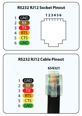
2) "source" a RJ11 (4P4C) terminated curly wire...
3) replace the RJ12 (6P6C) plug on my pier with a RJ11 plug
4) Call it a day and be happy that it works.


I think I have uncovered a new way to have my cake and eat it too.

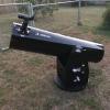
Since this is, at its core, all about remotely driving my CGEM mount from a dedicated imaging/observatory PC/Laptop from a warm "enclosed" position some 40' from the pier... While not having a rats nest of cables, controllers, dongles at the pier.

Lets consider this:
Step one: I take the HC, and put it away, safe in its foam lined box.
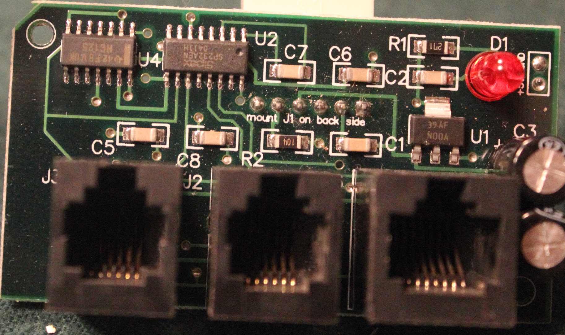
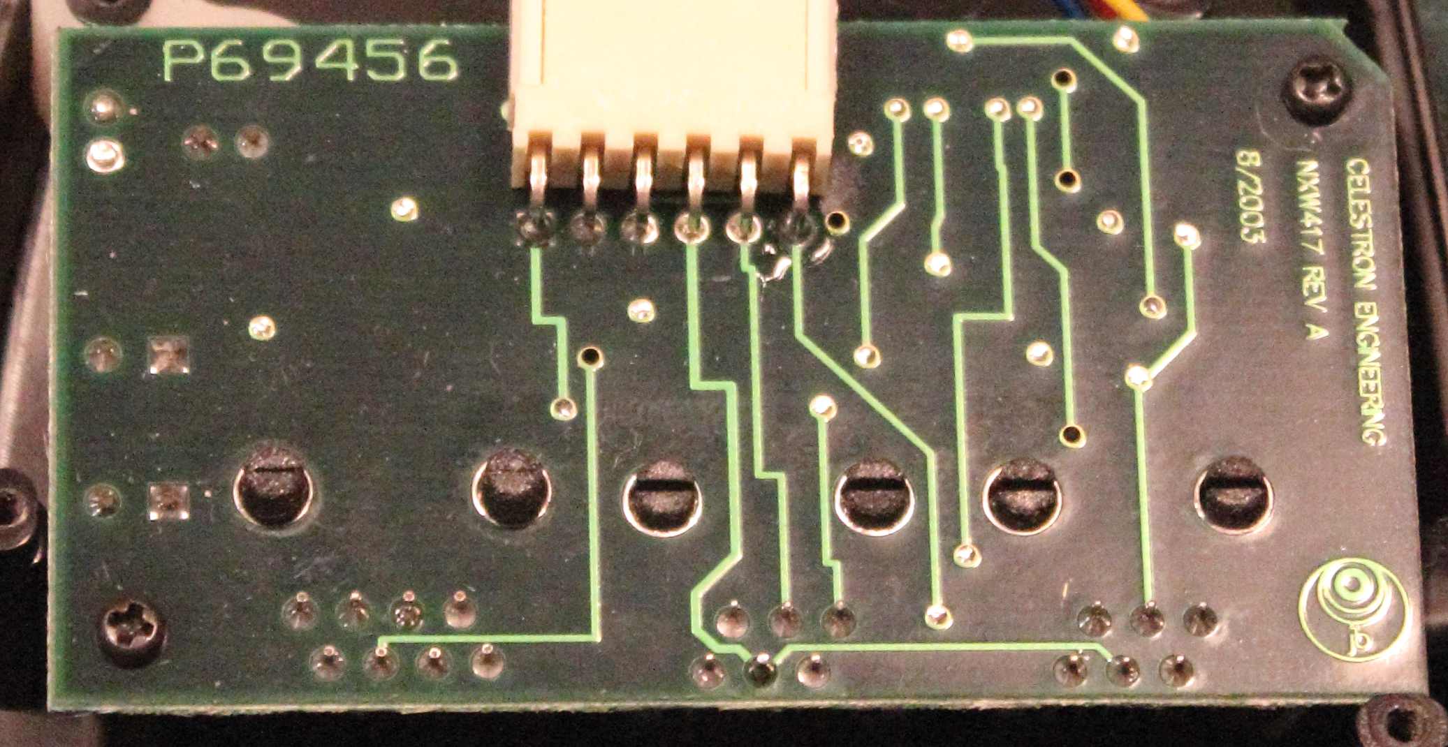
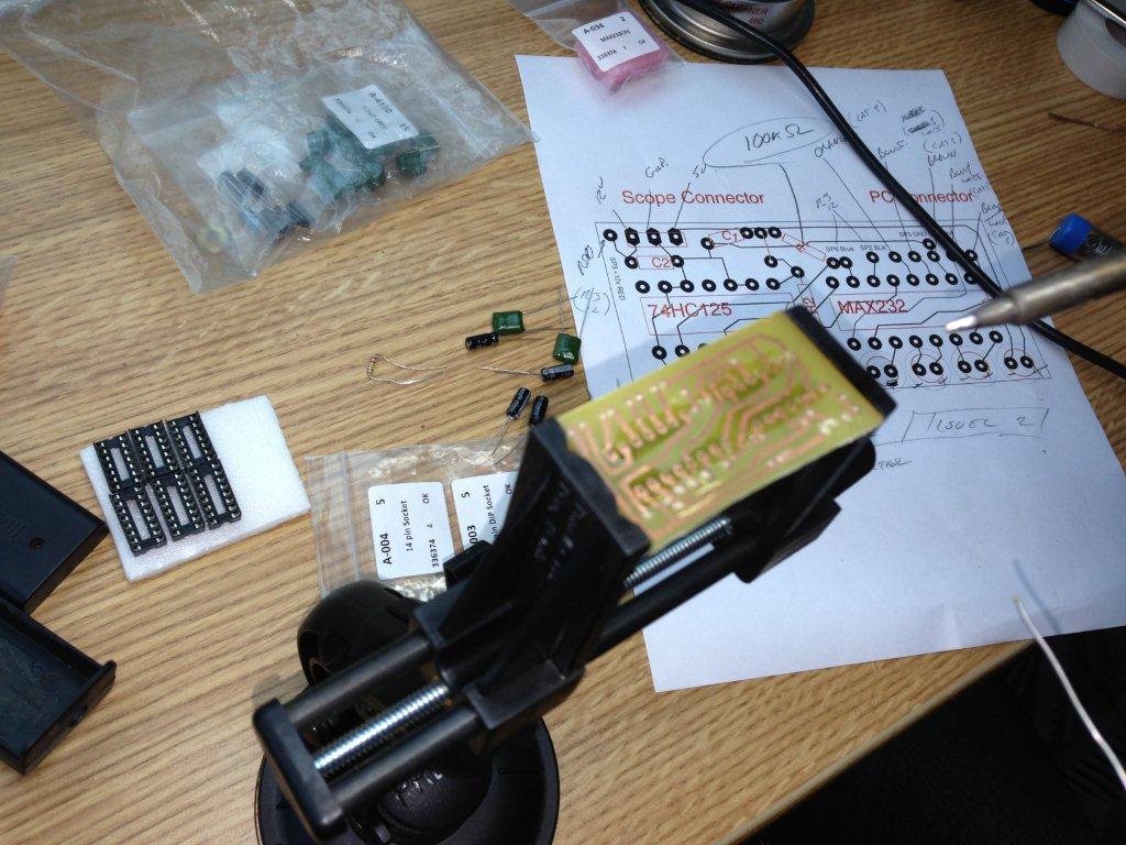
Step two: I run a 40' serial signal to the mount on the pier over a Cat6 cable and a homebrew Celestron PC Port Converter...
Step three: On the PC/Laptop I run my copy of NexRemote to drive the mount over the wire in step two... I will use NexRemote, to store alignments, park the mount, hibernate, etc.
Step four: On NexRemote I activate a virtual port and I use that to link to TheSky (since I really like that point and go interface)

So far that is pretty straight forward right?

Step five: So I'm thinking how to I align with a tethered PC running NexRemote that is about 40' from the eye piece... Wireless GamePad anyone? I'm sure one of the geeks at work is likely to have something that I can borrow and test.


So lets see:
Less cabling (at least at the pier)? Check
Less things to setup and take down at the pier? Check
Engineering Elegance? at the pier Check... at the PC? Not really
One less unsecured kinda expensive sensitive gizmo to be left outside? Check
Will it work? testing underway...

I wonder what the max range of a wireless gamepad is...
So close and yet so far away...


Been doing this for multiple years now.. I use a Logitech F710 wireless remote, nexremote with theskyx talking to the virtual port on nexremote.

You can even have nexremote connect to your favorite serial over wifi device, skysafari, skyq, bluetooth, etc.

#52 ur7x

ur7x

    Viking 1

  • -----
  • topic starter
  • Posts: 788
  • Joined: 08 Jan 2012

Posted 23 July 2013 - 04:27 PM


Been doing this for multiple years now.. I use a Logitech F710 wireless remote, nexremote with theskyx talking to the virtual port on nexremote.

You can even have nexremote connect to your favorite serial over wifi device, skysafari, skyq, bluetooth, etc.


What sort of range are you getting on the F710?

Some sites report connectivity problems at a few feet.. Some report that they can run these things 30+' away from the PC... The XBox remotes seem to have better range reviews some stating that they can run as much as 50' away from the PC.

I would have pretty much clear line of sight between the pier and the remote location.

#53 wolfman_4_ever

wolfman_4_ever

    Apollo

  • -----
  • Posts: 1,245
  • Joined: 15 Jul 2011
  • Loc: El Segundo, Ca, So. Cal

Posted 23 July 2013 - 07:18 PM

I have a Pod Observatory.. I'm never farther away than 8ft.

#54 frito

frito

    Apollo

  • *****
  • Posts: 1,496
  • Joined: 05 Oct 2012
  • Loc: Fremont, CA

Posted 23 July 2013 - 11:00 PM

range on common wireless RF devices can be impacted by many things, walls, material walls are constructed from and other RF devices operating on the same frequencies in the same local area are all factors. generally speaking RF controllers like the 360's use the same band Bluetooth and common wireless phones use, not to mention wifi as well so range can and will vary but as long as you are within a reasonable distance of the receiver it should work reliably. 30-50 feet is not what i would in my experience consider a reasonable distance, 20 feet or less is more realistic most of the time.

#55 Jmel

Jmel

    Vostok 1

  • -----
  • Posts: 101
  • Joined: 24 Jan 2012
  • Loc: Eastern North Carolina

Posted 30 July 2013 - 01:53 PM

Funny stumbling across this thread. My coworker is making me a converter box in the office next to mine as I type this.

I myself have had a similar idea to yours, and I'll lay out what I am thinking, what I've done, and maybe we can collaborate...

I have a cg5 mount. I also have a laptop that runs the mount as well as handling the imaging. I also have an android tablet.

Here is my intended setup:

Mount connected via converter box and serial/usb prolific adapter. Then to a usb hub, then to laptop.

Also connected to usb hub is the Canon 1000D I use for imaging, as well as a gpslim 236 (with proprietary usb cable, though you could use it via bluetooth), and soon, in a few days, a temperhum usb stick.

On a secondary usb port on the laptop, an orion starshoot autoguider (of the magnificent mini autoguider package). This is due to the high bandwidth requirements of autoguiding.

On my pc, I run backyardeos for imaging/virtual illuminated reticle. PHD for guiding. Nexremote and nexgps for mount alignment. Alignmaster for polar alignment assistance. Stellarium and stellarium scope for one click 'goto' without having to use the hand controller. Astrotortilla for relocating specific spots in the sky I was imaging the night before (or the week before)...

I also use an app called "wifi scope" which allows ip based wifi control of the mount (using ascom) so that I can use skysafari pro on my tablet or phone for "goto's". This works pretty well, but took a little configuring on the skysafari end that I didn't anticipate.

The plan? Well, I go outside to my site (drive the truck, unload etc). I do a rough polar alignment on the scope, hook up all my power, and cables (I have them in a big fat wire loom now, for simplicity). Then, after starting the laptop and the software conglomeration, I close the lid (it doesn't go to sleep) and go inside where it's warm. I fire up team viewer (free btw, for lan use too) on the android tablet, and connect to the laptop via wifi. For this I use the built in (to my laptop) "my wifi" app, that turns my laptop into an access point. Next thing I know, I'm looking at a remote desktop of the laptop. Too small on the 7" screen? Well, I hook my tablet up to hdmi and use the bluetooth mouse and usb keyboard I bought for it.

Now we're makin bacon!

I was hoping to find a way to connect the gpslim 236 from holux directly to the mount, but right now that seems kinda pointless as it's more work researching cabling than I want to put into it.

#56 ur7x

ur7x

    Viking 1

  • -----
  • topic starter
  • Posts: 788
  • Joined: 08 Jan 2012

Posted 30 July 2013 - 07:16 PM

Aren't co-workers great! Subordinates are even better...

Yes you and I are on the same page... other than I plan to run mine on a permanent pier... And I have a laptop with an actual old school serial port...

Are you building the converter with a perforated board... or are you etching a customer Printed Circuit board?

If you are etching... I would love to see/share your PC design... I'm on the road to build a etched PC board next week.

#57 Jmel

Jmel

    Vostok 1

  • -----
  • Posts: 101
  • Joined: 24 Jan 2012
  • Loc: Eastern North Carolina

Posted 30 July 2013 - 08:18 PM

perforated... I didn't know the other existed... I'd have loved to have recreated the celestron adapter with 2 aux and a PC port though.

#58 frito

frito

    Apollo

  • *****
  • Posts: 1,496
  • Joined: 05 Oct 2012
  • Loc: Fremont, CA

Posted 31 July 2013 - 12:28 AM

pcb etching is messy but great, used to do it in high school electronics class back in the late 90's, i bet they don't allow it these days due to the chemicals (ferric cloride) I know you can buy the stuff still, my local electronics store sells ferric cloride as well as copper clad PCB blanks and small tanks, i don't build enough custom PCBs to warrant buying the stuff and when i need to build something i just go with a breadboard becase its cheaper for one off stuff thats not complicated but having a real PCB to work with can help emmensely with building home made circuit boards for sure.

#59 Jmel

Jmel

    Vostok 1

  • -----
  • Posts: 101
  • Joined: 24 Jan 2012
  • Loc: Eastern North Carolina

Posted 31 July 2013 - 10:45 PM

Aren't co-workers great! Subordinates are even better...

Yes you and I are on the same page... other than I plan to run mine on a permanent pier... And I have a laptop with an actual old school serial port...

Are you building the converter with a perforated board... or are you etching a customer Printed Circuit board?

If you are etching... I would love to see/share your PC design... I'm on the road to build a etched PC board next week.


Went to test tonight on a spare mount I have, and it looks like perhaps V+ and C1+ were accidentally connected to each other with solder. I started checking the board when I noticed no communication from the pc to the mount after plugging it in.

(EDIT: this may not be the issue, I'm still trying to see what is going on with the circuit... testing all points tonight).

On the bright side, my mount is not fried, nor is my usb to serial adapter smoking away.

Hopefully he can remove the solder tomorrow and it didn't hurt anything during my testing.

If not, I'll chalk it up to a learning experience, and get one of those posieden (sp?) boxes from germany and just not deal with the work of getting the box made. My friend said the rj12 cable was the worst; it was stranded copper and very tiny. The last wire he soldered is the one where I think he accidentally jumpered the pins I stated above.

EDIT: Looks like my friend had it right, and the tiny part that I was supposed to do was wrong. I had pins 6 and 8 confused on the diagram for the serial port connection. I realized this by going back to the nexstar site and looking at the "pc cable". The font that was used on the schematic page at the end was hard to decipher. It's working perfectly now, and I'm very happy that I can leave the stupid hand controller at home. :jump:

#60 ur7x

ur7x

    Viking 1

  • -----
  • topic starter
  • Posts: 788
  • Joined: 08 Jan 2012

Posted 03 August 2013 - 10:42 AM

Wow... Nice work... I have now laid out a custom PC board for this project and will etch one next week at work. With little effort I got it all down to a board about 1"x2"...

I will post .ai, .pdf, .jpg files once I test it for anyone to copy.

I also have managed to get the hat/rocker/POV switch on my Xbox controller to drive the scope now too!

Simply down load a freeware Game Controller keyboard mapper (I'm using Xpadder) and assign the keyboard arrow keys to the POV switch and now those buttons are active too.

If you want your cake and eat it too (and this is the theme of this thread) then you assign "shift arrow" keys to the rocker/POV shitch and the joystick will drive the scope at the set slew speed and the POV switch will drive the scope at the full "9"...

Oh and I discovered a small bug with the NexRemote software!

When you drive the mount using assigned "FastUp" "FastDown" "FastLeft" or "FastRight" assigned buttons or keys the virtual display does not flash rate "9" in the corner, it reports that it is moving the scope at the preset (likely slower) rate. The good news is that buttons do work and it will move the scope at the faster rate...

#61 Jmel

Jmel

    Vostok 1

  • -----
  • Posts: 101
  • Joined: 24 Jan 2012
  • Loc: Eastern North Carolina

Posted 05 August 2013 - 08:11 AM

Wow, that is awesome ur7x! I'm eager to see your posts.

I would really have liked to have incorporated a couple of things into a replacement circuit, if I had the time. One would have been a built in aux splitter, to hook up a gps if one so chose... the other would have been to have incorporated a serial to usb adapter - but on the second point, I realize this may not be as good as it sounds; I understand there are limits not only on the usb length, but also on the length of the cable from the mount to the converter. Serial has the longest length limits.

I was struggling to get both joysticks working. It would have been nice to have a trigger set to shift (not a shoulder button), or to have one stick slew at 9 and the other at a slower slew. I won't be using the joystick much though, it was just fun to play with.

#62 ur7x

ur7x

    Viking 1

  • -----
  • topic starter
  • Posts: 788
  • Joined: 08 Jan 2012

Posted 06 August 2013 - 03:56 PM

Regarding "extra" aux port if you are to believe the various CGEM and ASGT wiring diagrams all over the place.

A simple 6 connector RJ11/RJ12 splitter with a jumper over pins 2 and 4 should produce your extra aux port.
http://www.cloudynig...lestron HC a...

Take care with the jumper since pin 3 is +12V and that will not mix well with the sensitive CMOS level signal on pins 1,2,4 and 6

#63 Jmel

Jmel

    Vostok 1

  • -----
  • Posts: 101
  • Joined: 24 Jan 2012
  • Loc: Eastern North Carolina

Posted 07 August 2013 - 10:49 AM

I was going to use a surface mount dual rj12 jack from monoprice, but they have some weird color scheme going on, I'll have to number the pins with labels before working with the innards. I was going to mount the box to the head of the cg5 mount, with a 6 inch rj12 flat cable going to it. Then, the converter box would attach to the surface mount 'splitter' leaving another aux port, just in case.


What would be helpful is a pin number to pin number diagram... The 'icons' in that diagram you pasted (which I saw on this thread: http://www.cloudynig...3870386/Main... ) are a little misleading to a non-electronics guy like myself... orientation specifically... I don't want anything to be reversed...

http://www.commandfu...s232_pinout.png

#64 ur7x

ur7x

    Viking 1

  • -----
  • topic starter
  • Posts: 788
  • Joined: 08 Jan 2012

Posted 07 August 2013 - 09:04 PM

In your pinout link those are the same... The male connector is pictured top down and the female is bottom up... Or in other words... to plug one into the other, one needs to be turned over.

The only wire that should give you pause is the 12V red one... don't screw that one up... the others will not cause damage.

Of course Celestron Pinouts are different then your post. The use a TTL/CMOS signal at the scope, NOT RS232

#65 Jmel

Jmel

    Vostok 1

  • -----
  • Posts: 101
  • Joined: 24 Jan 2012
  • Loc: Eastern North Carolina

Posted 10 August 2013 - 10:08 PM

I think I'll work on that tomorrow. However, I believe the GPSlim 236 from Holux (which is what I'd use, since I have one currently hooked up to pc and connected to NexGPS) is already outputting TTL...

Here is the manual:

http://www.holux.com...ile/3205400.pdf

"4.6. Output and Interface
z Output
I. Output protocol
Baud Rate: 38400 bps
Data bit: 8
Parity: No
Stop bit: 1
II. Format. NMEA0183 V2.2: GPGGA (1time/1 sec), GPGSA (1 time/5 sec.),
GPGSV (1time /5 sec.), GPRMC (1time /1 sec.), GPVTG (1 time/1 sec), (GLL,
or SiRF binary format for optional).
III. Datum: WGS84.
z Input/ Output Interface:
I. Compatible Bluetooth Serial Port Profile (SPP), Version1.1 and class 2(up
to 10 meter range).
II. In/Out Port. GPS signal (Out)/Command(In) with CMOS/TTL Level。"

I have the usb to serial cable, which is essentially a prolific serial to usb adapter built into a chip near the usb plug on the computer side:

Table 1
Pin Pin Name Signal and description
1 GND Signal ground, Battery charging ground.
2 VOUT Unregulated voltage out: 3.6 V max 100mA.
3 TXD
Transmit Data. From organizer to peripheral.(Voltage Level is 3.3V ~
5.0V).
4 RXD
Receive Data. Form peripheral to organizer.(Voltage level is 3.3V ~
5.0V).
5 VCHARG
Positive terminal of DC adaptor that powers the internal charging
circuit of Li-Ion battery. The approved power supply is 5.0V +/-
5%@1A.

#66 ur7x

ur7x

    Viking 1

  • -----
  • topic starter
  • Posts: 788
  • Joined: 08 Jan 2012

Posted 19 August 2013 - 04:03 PM

Understand that two things need to happen here to make this work...

First you need to get the two devices (mount and GPS receiver) to "talk" over the right pinouts at the expected TTL/CMOS levels.

Second you need to get the mount and the peripheral to basically speak the same language.

Celestrons communication protocol is detailed (at least in part) here:

http://www.celestron...starcommprot...


You can see, as you might expect, that there are some rules as to how the mount talks to the hand controller or other attachments... It expects the device to say "Hey, here comes some GPS coordinates" before it sends three (or four) large number sets that denote log, lat, and date/time.

And there is a handshake protocol where the mount after successfully getting the correct information basically says "Thanks, I'm good"

Of course the "Hey, here comes some GPS coordinates" can be as simple as the letter "W" and the "Thanks" can be as simple as "#"

But if this info isn't there it will be like your GPS receiver is speaking German and the mount is speaking Chinese.

I would not just randomly start plugging things into the HC or AUX port unless the manufacture and/or Celestron certifies the device will work.

#67 Jmel

Jmel

    Vostok 1

  • -----
  • Posts: 101
  • Joined: 24 Jan 2012
  • Loc: Eastern North Carolina

Posted 19 August 2013 - 06:20 PM

Agreed... I guess I will continue to use the gps on the pc from here on out. If there was a hardware device that was inexpensive that expected serial output of a gps and could translate to the mount, I'd buy it. But typically these types of devices (if they exist) are not inexpensive.

#68 ur7x

ur7x

    Viking 1

  • -----
  • topic starter
  • Posts: 788
  • Joined: 08 Jan 2012

Posted 10 October 2013 - 10:16 PM

Bringing this thread back from the dead....

I have updates...

It took me months but I etched a PC board, bought all of the necessary IC's, Capacitors, cables, connectors, and what not... All of the bits and pieces can be easily sourced for less than $10 if you are willing to wait 20 days of shipping from the far east.

Completed soldering the whole thing today...

I have pictures of all of it that I will happily post and I have PDF's and other formats of my PC board that I will also share...

Also of interest, while I was waiting for parts... a unused #93965 converter came up for sale on flee-bay and I scooped it. It is shipping slower than the second coming, as I watch it track through several USPS sorting facilities on the wrong side of the continent... I suspect I won't have it till after Columbus Day...

My plan is to first get this all working with the #93965...

If it works I may never plug in my home brew version of the #93965... Frankly I'm not all that interested in risking either mount on this circuit... If the #93965 doesn't work I will likely give up and drive it through the HC which I know works.

If it does work... then I will probably build a 12V power connecter/tester to make sure that the voltages are all with in the comfortable range before I risk my mount.

The guys at work, who helped me build this thing are taking an office pool if I will be able to wait to do the necessary testing or if I will just chance it.

#69 dmdouglass

dmdouglass

    Vanguard

  • *****
  • Posts: 2,128
  • Joined: 23 Dec 2007
  • Loc: Tempe, AZ

Posted 10 October 2013 - 11:22 PM

Keep us posted...

#70 ur7x

ur7x

    Viking 1

  • -----
  • topic starter
  • Posts: 788
  • Joined: 08 Jan 2012

Posted 19 October 2013 - 09:15 PM

Update... So my little 93965 arrived... and while it did cross the continent its path seemed as simple and as fast as Hannibal's crossing of the Alps... Be that as it may... the second thing I did when I got this "newish" box home... was take it apart... the first thing was to make sure it works.

So here are what the front of guts look like:

Attached Thumbnails

  • 6147517-frontsmall.jpg


#71 ur7x

ur7x

    Viking 1

  • -----
  • topic starter
  • Posts: 788
  • Joined: 08 Jan 2012

Posted 19 October 2013 - 09:25 PM

And the back looks likes like this...

Attached Thumbnails

  • 6147537-back.jpg


#72 ur7x

ur7x

    Viking 1

  • -----
  • topic starter
  • Posts: 788
  • Joined: 08 Jan 2012

Posted 19 October 2013 - 09:45 PM

This should solve a lot of the mysteries about the Aux ports and the home built converters...

First off this little OE gizmo's has two IC's and a voltage regulator just like the "home brew" version... and the two IC's are a Max232 and an 74HC125... and the Voltage regulator is a simple 12V-5V regulator... so far so good... interesting that the Home brew has 2 resistors... this one technically has 2 as well... but one is required to support the LED... so really it only has one... And the Home brew has 6 capacitors and this thing has 8! It looks like some of those capacitors might come into play in the Aux split... Maybe they act a form of voltage spike protection that can occur when you plug and unplug things...

And while most of the interesting traces are hidden by the RJ45 and RJ12 connectors... The ones that we can see don't match the Home brew schematic... For example in the photos you can see that pin 9 of the Max232 seems to go to pin 13 of the 74HC125 and yet the wiring diagram has pin 9 going to pins 1 & 4 of the buffer chip... If you follow some of the traces the HC125 chip and at least one of the capacitors is involved in the Aux split... looks like the Aux split is a little more complicated then originally thought too.

With this knowledge in hand.. and after testing that the signal ports on the telescope side of my home built converter weren't outputting more than 5V's I plugged it into my laptop and scope and no surprise... It didn't work... and it didn't do any damage either..

Back to the test of the 93965 with NexRemote...

In short.. Wow.. works fine over a long haul (35') Cat 6 wire... telescope slews, tracks, hibernates and homes with direction from the remote laptop like it was being driven from a hand controller. Mission accomplished... too bad that I couldn't get the home brew to work... The good news is I only wasted about $6 building the thing...

Celestron should consider bringing this back as part of a pier adapter kit for some of their "heavier" mounts.

#73 ur7x

ur7x

    Viking 1

  • -----
  • topic starter
  • Posts: 788
  • Joined: 08 Jan 2012

Posted 23 October 2013 - 07:58 PM

Another update.

Not able to leave well enough alone, the two circuits were sent to my radio shop at work to see why one works and one didn't

An employee of mine who understands TTL circuits and IC logic way better than me took a look at both and specifically at the Homebrew circuit... His observation is that the Homebrew should work.

Turns out that as a result of initially installing the 12-5v rectifier backwards I had fried the 74HC125 buffer chip... I swapped that out... and tada... the home brew came to life.

I will post pics and Pdf versions of the PC board tomorrow.

With a little effort this can be made small enough to fit inside of a 2XAA battery box.

#74 ur7x

ur7x

    Viking 1

  • -----
  • topic starter
  • Posts: 788
  • Joined: 08 Jan 2012

Posted 24 October 2013 - 11:32 AM

So now that I actually have my version of the Home brew working I feel a little more comfortable posting photos.

Here is the PC board in the vice ready to be soldered.

Attached Thumbnails

  • 6155454-Homebrew PC board.jpg

  • daslolo likes this

#75 ur7x

ur7x

    Viking 1

  • -----
  • topic starter
  • Posts: 788
  • Joined: 08 Jan 2012

Posted 24 October 2013 - 11:36 AM

And here is a PDF version of the PC board.

You will see that there are two versions the one in the vice is the smaller one on the right. Since then I moved the 12V rectifier to a more open spot of the board... in version 1.0 it is too jammed up with the buffering capacitors and with its heat sink it is too tall to fit in the 2XAA box that I got on ebay for 99 cents.


In version 2.0 the rectifier has enough room to be bent over and lie flat.

I have tested and can confirm that this circuit works great with both my CGEM and ASGT.

Of course as always... double check your work, and use at your own risk...

If you are following this... on my first attempt I installed the rectifier backwards and was pushing a full 12V through the whole circuit. This fired the 74HC125. Of course if it had of been attached to the scope at the time it would have likely fired something in the scope too...

BEFORE you plug anything like this to your scope, attach it to an external 12V power supply (jumped with the right polarity to the red and yellow RJ12 wires from the scope) and read the volage levels coming back to the scope on the blue, black and green wires... if you see ANYTHING over 5v STOP, and figure out what is wrong.

If anyone wants the native drawing of the PC board or a list of components and cheap ebay vendors to supply them... PM me and I will happily provide them.

I literally bought enough parts to build two of these for about $8.

Attached Files


CNers have asked about a donation box for Cloudy Nights over the years, so here you go. Donation is not required by any means, so please enjoy your stay.


Recent Topics


Cloudy Nights LLC
Cloudy Nights Sponsor: Astronomics