Collimation and Star Symmetry
#1
Posted 30 November 2013 - 11:25 AM
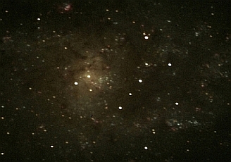
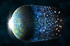
The full image when presented at a 50% reduction actually looks quite good - but there is an underlying problem here that needs to be resolved. The scope was collimated using a set of Catseye Tools at f/5 prior to inserting my ASA 0.73X focal reducer.
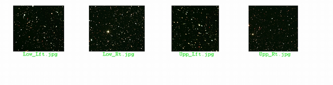
Images recorded with the ASA corrector installed and the default alignment (generated by the Catseye Tools) show oblate stars. The image posted here was "improved" by making small corrections at the PM to improve star symmetry. As you can see, the final result is marginal at best. With additional effort I am sure it could be further improved.
I felt justified adjusting the PM alignment since it is at least possible that the corrector introduced some tilt that was not present during the original collimation performed without it. Is this a reasonable way to proceed? Also, is there a systematic way to impart PM adjustments with the only feedback being the star field displayed on the monitor? With three adjusters on the PM and two directions (CW and CCW) it is easy to walk way off when trying to improve things.
Peter
#2
Posted 30 November 2013 - 11:50 AM
If the elongation shown here is indeed representative of what the *optics* are producing, that is quite bad.
Is there a way to differentially rotate the reducer? This should reveal if it has tilt, wedge, or some other problem.
Are you certain you have no sag at the attachments?
And in general, I feel final collimation should be performed in the as-used configuration.
#3
Posted 30 November 2013 - 01:48 PM
#4
Posted 30 November 2013 - 03:21 PM
Found some poster somewhere on the ap-ug mailing list who said that the spacing should not exceed 65mm, but as low as 63mm can be tolerated.
I've adjusted my Baader VariLock to give 65mm, will see how that goes..
#5
Posted 30 November 2013 - 05:58 PM
Good luck with the revised spacing between the corrector and the focal plane. I have experimented with this as well - though I have not found that it improved the on axis performance of the telescope/corrector system. I actually had the corrector re-aligned (at the manufacturer) thinking it had a tilted or otherwise misaligned component. This did not provide any improvement in imaging performance.
Generally, I consider myself to be good at collimation. I never seem to have these problems when using the scope visually, but imaging in another story. I am beginning to suspect that the wall thickness (0.030") of my steel tubed Newt is insufficient to hold collimation. The problem with this reasoning is that I can NEVER get acceptable stars even when I attempt to optimize collimation for a given target.
I get good agreement between the Catseye tools and my laser collimator. The problem is that this never translates into properly formed stars. To be brutally honest, the on axis performance even with the reducer removed is not "perfect".
With the rare exception of a few "gifted imagers", I usually see this same problem to varying degrees on most Newtonian images. I do not plan to give up, since I really like the attributes of Newts. I just hope I can achieve this goal in one human lifetime.
Peter
#6
Posted 30 November 2013 - 11:06 PM
Here are small crops from the corners of an image taken with the scope ans ASA corrector. The sensor has an APSC form factor so the edges may be at the limit of the corrected zone for the 2" ASA corrector. Next time out I try rotating the camera/corrector. Using CCD Inspector, the total tilt comes in at 12% for this image. It shows collimation good to 7 arc-sec.
Peter
#7
Posted 01 December 2013 - 02:20 AM
I have seen some pretty good Newt images though with the Baader or Paracorr. Maybe there's something about the Keller that you and i don't know?
This is what I did to my steel-tube newt:
I think it can hold collimation well enough, because when I pull/tug on the focuser while watching the CCD live view, the stars return to their normal locations.
One other thing we can try - if you can find a local sheet metal shop, ask them to roll a piece of maybe 1mm or 2mm steel plate to the ID of your tube, then put that plate inside. This is going to be my next move. Then put a few holes in the existing tube to attach the inner steel plate.
That, and get a Feathertouch focuser. I'm still using the stock CPC linear bearing crayford.
That said you are right.. even on-axis my stars aren't round (with the corrector in place). I should try rotating it and see if the "tails" on the stars change direction.
I've been using the AT8IN + Keller though, here are a few photos..
One can see the non-round stars even at these reduced image sizes.
(and no, these are not tracking errors.. a Mach1 at 600mm focal length does not have tracking errors)
#8
Posted 01 December 2013 - 09:24 AM
That's a very good idea. I think it would definitively confirm or exclude out-of-square elements of the corrector optics.
#9
Posted 01 December 2013 - 12:08 PM
#10
Posted 01 December 2013 - 12:56 PM
I purchased an aluminum tube from the Hastings company to replace my current thin-walled steel tube. The new tube has a wall thickness of 0.094" and is significantly stiffer than the OEM tube. Apparently we have been thinking along the same lines - specifically that the tube stiffness needs to be improved.
It is curious that Jason is working with similar hardware and does not experience the same problems. On the other hand, he is not operating with the ASA corrector in the mix.
It is my opinion that the corrector is not the only problem. If I remove the corrector and critically examine the on-axis performance of my telescope it still does not fully meet expectations. Obviously, as you extend to the edges of the field, coma really degrades star shape.
I should point out that all of our collimation work occurs with a light weight laser or collimation tool in the focuser. When imaging, we transition to a (at least in my case) from a single "tool" to a camera, filter wheel and corrector. Additionally, this stack is long so it potentially couples in some undesired moments into the telescope tube/focuser. I suspect that we are not ever operating with the alignment we originally established.
The added weight would tend to de-collimate at the focuser end of the telescope not at the PM end. My efforts to improve the imaging performance at the "system level" have been limited to adjustments made with the PM. It seems that the offending component may actually be the secondary mirror. Angular errors at the secondary can not be mitigated using angular corrections imparted with the PM.
Now the question is, is there a way to meaningfully "tune" the angular position of the secondary mirror with all of the imaging hardware in place? Based on my experience, this will be difficult since the control over SM angular position is very coarse. I would bet that playing with this adjustment without feedback from a "tool" is walking further into the quick sand. On the other hand, we may already be in the quick sand!
Peter
#11
Posted 01 December 2013 - 01:25 PM
#12
Posted 01 December 2013 - 01:35 PM
I do notice that the star moves a bit when I lock down the focuser. I suspect that the locking screw is tilting the entire focuser drawtube. Maybe it's time for a Feather touch...
#14
Posted 01 December 2013 - 02:10 PM
What I've seen is that when I move the primary the stars move around but their shape doesn't change.
Here's an issue I found (just recorded it)
http://www.youtube.c...h?v=I9BPqL8QZNg
if i wiggle the focuser around, the shadow of the primary center donut doesn't move (obviously, this is the virtue of the barlowed laser) but it's obvious that collimation is affected by the focuser wiggling around.
#15
Posted 01 December 2013 - 03:43 PM
Though this process helps, it does not rapidly and efficiently converge on a final alignment solution. You are essentially chasing your tail trying to improve things. I think the weight of the camera and other accessories compromise the collimation making this step necessary. My question remains, should the adjustments be made at the secondary mirror since this is probably the source of the "alleged" mis-collimation.
Peter
#16
Posted 01 December 2013 - 06:32 PM
Good suggestion. I will try this out ASAP.
Peter
#17
Posted 02 December 2013 - 12:45 AM
#18
Posted 02 December 2013 - 07:54 PM
The true check would be to collimate the scope as usual and then verify collimation with a weight added to the focuser(as Glenn suggested). The weight obviously should approximate the weight of the imaging hardware you use. You can try this using your laser.
Peter
#19
Posted 02 December 2013 - 09:47 PM
http://www.youtube.c...d&v=TTGCutUicp4
Peter
#20
Posted 02 December 2013 - 11:03 PM
#21
Posted 02 December 2013 - 11:04 PM
I'm putting together a 8" f/6 scope and just cut some rings for the ends. It's obvious that the scope goes out of collimation (using a laser) without the rings. With the rings, there is no noticeable movement when tilting the scope. I'm using a Hastings 10" tube with .064 thick walls.
I'm using a Moonlite focuser and there does seem to be a small amount of slop/flex in the 2" drawtube. If I lightly push on the laser in the drawtube, I can see the laser move. I suppose if I collimate on a star near my intended target, the slop in the focuser should be minimal. It just doesn't inspire a lot of confidence.
#22
Posted 03 December 2013 - 12:27 AM
also I have a Feathertouch on the way..
#23
Posted 03 December 2013 - 02:29 AM
#24
Posted 04 December 2013 - 11:30 AM
By imparting very small motions, I was able to "stumble" on a position that provided round stars and an essentially flat field even with the ASA coma corrector installed. I am happy with the last nights imaging performance though I wonder about my ability maintain or recreate it.
I need a way to walk into this alignment using the collimation tools as opposed to random tweaks imparted to the full up telescope prior to imaging. Though it worked out great last night, I can envision (more often than not) making matters worse. Even a well made secondary/spider has poor angular dynamics compared to the behavior of a typical PM cell.
I still have to try out Glenn's suggestion of collimating with a suspended weight to mimic the effect of the imaging hardware. Since my mount can carry it, I will soon be going for a much more rigid (and heavy) telescope tube to combat this nonsense. I wish you could order a telescope "build to design" so that the customer can select the specific hardware elements that go into the delivered unit. I surely would never "intentionally specify" a 0.030" thick steel tube to support an imaging Newtonian (or visual for that matter).
Properly designed systems do exist if you are willing to pay around $5,000.00 (or more) for an 8" Newt. Why are there no vendors that attempt improve on the standard, affordable imaging Newtonians in meaningful way? How big of a deal is it to provide a stable tube?
Do the vendors feel that weight savings is more important than stability?
Peter
#25
Posted 04 December 2013 - 04:28 PM
If you are a mfr of scopes, you quickly realize your barriers to sales are price and weight. So you do what you can to reduce both. Does that compromise stability? Yes. But it increases sales.I collimated my Newtonian then added the imaging hardware and slewed to a target. As usual, the image quality was compromised by oblate stars even at the center of field. This time I attempted to improve star symmetry by making adjustments at the secondary mirror and not the primary.
By imparting very small motions, I was able to "stumble" on a position that provided round stars and an essentially flat field even with the ASA coma corrector installed. I am happy with the last nights imaging performance though I wonder about my ability maintain or recreate it.
I need a way to walk into this alignment using the collimation tools as opposed to random tweaks imparted to the full up telescope prior to imaging. Though it worked out great last night, I can envision (more often than not) making matters worse. Even a well made secondary/spider has poor angular dynamics compared to the behavior of a typical PM cell.
I still have to try out Glenn's suggestion of collimating with a suspended weight to mimic the effect of the imaging hardware. Since my mount can carry it, I will soon be going for a much more rigid (and heavy) telescope tube to combat this nonsense. I wish you could order a telescope "build to design" so that the customer can select the specific hardware elements that go into the delivered unit. I surely would never "intentionally specify" a 0.030" thick steel tube to support an imaging Newtonian (or visual for that matter).
Properly designed systems do exist if you are willing to pay around $5,000.00 (or more) for an 8" Newt. Why are there no vendors that attempt improve on the standard, affordable imaging Newtonians in meaningful way? How big of a deal is it to provide a stable tube?
Do the vendors feel that weight savings is more important than stability?
Peter
As a prime example, I've seen 10" newtonians sold on $700 mounts. That size OTA belongs on a $6000+ mount, and the $700 mount shouldn't have a scope bigger than 6" on it. But sales, not use in the field, is what matters to manufacturers.
What can you do about it? Buy something heavier with more rigidity (they exist) or from a company that will build to your specs (as I did), or become an ATM and do it yourself. Imagers usually go through a learning curve that is very steep. If they stay with it, they usually move into big, heavy, expensive mounts, and reinforced OTAs with bullet-proof focusers.
Expect to pay a lot for that, though. You can pay less, but you will have to learn how to overhaul and tune-up whatever you buy. Reinforcing a tube is just one of many such modifications.