
127mm f/5.5 binocular
Started by
Mr. Bill
, Jun 08 2012 01:52 PM
183 replies to this topic
#51

Mr. Bill
-

-
topic starter
- Posts: 9,823
- Joined: 09 Feb 2005
Cosmos
Posted 01 July 2012 - 01:48 PM
Hey, just made Postmaster.....only took 7 1/2 years.
#52
marcelof
-

-

- Posts: 310
- Joined: 24 May 2010
Ranger 4
Posted 01 July 2012 - 01:51 PM
It is difficult to express with words.
I refer to this: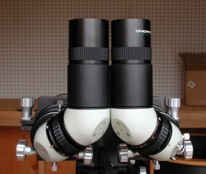
Only that constructed with the materials used by Mr. Bill.
I counted badly or only it uses two diagonal mirrors????
I refer to this:
Only that constructed with the materials used by Mr. Bill.
I counted badly or only it uses two diagonal mirrors????
#53
Rich V.
-
-

- Posts: 10,744
- Joined: 02 Jan 2005
Voyager 1
Posted 01 July 2012 - 02:06 PM
Marcelo, what you are talking about is the Matsumoto EMS mirror system. It's the ultimate solution for a bino back. Matsumoto uses an elegant 2-mirror system that produces a correct image. There's a lot more engineering and precision fabrication to it than using 2- 90° factory diagonals together as Bill has done, though.
Matsumoto EMS
Rich
Matsumoto EMS
Rich
#54
Mr. Bill
-
-
topic starter
- Posts: 9,823
- Joined: 09 Feb 2005
Cosmos
Posted 01 July 2012 - 02:27 PM
My understanding is that the EMS system only works well with relatively slow f ratios such as f/7 and higher.
My setup provides no vignetting and outstanding edge of field illumination on fast refractors using f/5 or in my case here f/5.5.
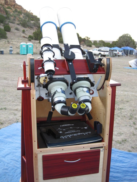
Here's a 6 inch f/8 Tak tubes system using the EMS. I took this last year at the Okie-Tex SP. Only cost $28K.

My setup provides no vignetting and outstanding edge of field illumination on fast refractors using f/5 or in my case here f/5.5.
Here's a 6 inch f/8 Tak tubes system using the EMS. I took this last year at the Okie-Tex SP. Only cost $28K.
Attached Thumbnails
#55
Wes James
-
-
- Posts: 5,505
- Joined: 12 Apr 2006
Fly Me to the Moon
Posted 01 July 2012 - 07:33 PM
...*drool*...
#56
Wes James
-
-
- Posts: 5,505
- Joined: 12 Apr 2006
Fly Me to the Moon
Posted 01 July 2012 - 07:33 PM
You've got an impressive project going here, Bill- Impressive!!
#57
marcelof
-
-
- Posts: 310
- Joined: 24 May 2010
Ranger 4
Posted 01 July 2012 - 08:47 PM
I supposed that eliminating the elliptical mirrors the beams they follow his path, placing then diagonals in the back part. The box should be little long mas. I do not have the elements to experiment, because of it I ask.
My experience says to me that eliminating the prisms a binocular remains much more luminous. Will it be more luminous than the fuji 150? Or maybe equal?
My experience says to me that eliminating the prisms a binocular remains much more luminous. Will it be more luminous than the fuji 150? Or maybe equal?
#58
mercedes_sl1970
-
-
- Posts: 578
- Joined: 02 Dec 2005
Viking 1
Posted 01 July 2012 - 11:01 PM
You've got an impressive project going here, Bill- Impressive!!
You'd think he would have it finished by now. It really is only a fairly trivial project....! (Yeah, right).
Andrew
ps I bet the bet the views will be fabulous
#59
GlennLeDrew
-
-

- Posts: 16,158
- Joined: 17 Jun 2008
James Webb Space Telescope
Posted 02 July 2012 - 05:46 AM
The elegance of the Matsumoto system lies only in the fact that that two mirrors deliver a normal, non mirror-reversed view. In other respects the system leaves much to be desired due to the fact that it requires the user to tweak things in order to have the eyepieces be parallel. That the erection/folding system effectively 'hangs out there' like a plumber's nightmare just waiting to be bumped and hence knocked out of collimation gives me the heebie-jeebies! This is NOT robust, by my engineering standards.
#60
Rich V.
-
-
- Posts: 10,744
- Joined: 02 Jan 2005
Voyager 1
Posted 02 July 2012 - 09:35 AM
Amen to that, Glenn! There's a whole lot going on mechanically with the EMS design compared to the sheer simplicity of this three mirror design.
I'm looking forward to looking through Bill's Bino Box!
Rich
I'm looking forward to looking through Bill's Bino Box!
Rich
#61
Wes James
-
-
- Posts: 5,505
- Joined: 12 Apr 2006
Fly Me to the Moon
Posted 02 July 2012 - 02:50 PM
So what kind of image does this bino box bino give- inverted/reversed?? Can't quite wrap my mind around the answer!! 
Wes
Wes
#62
GlennLeDrew
-
-
- Posts: 16,158
- Joined: 17 Jun 2008
James Webb Space Telescope
Posted 02 July 2012 - 03:15 PM
The view is just like that delivered by a refractor with a mirror diagonal installed--upright, but mirror-reversed L-R. The two following mirrors, due to the even number of reflections, do not alter the image orientation at all; their only purpose is to bring closer together, periscope-like, the widely separated optical axes.
#63
Mr. Bill
-
-
topic starter
- Posts: 9,823
- Joined: 09 Feb 2005
Cosmos
Posted 02 July 2012 - 04:58 PM
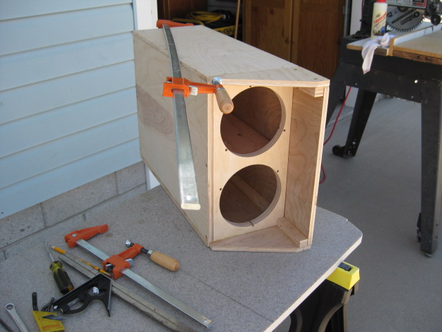
Last woodworking step....
Sanded, applied stain and letting everything sit overnight.
Tomorrow, flocking the interior and putting first coat of Urethene Spar Varnish on.
The end is in sight!
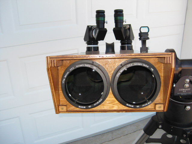
Notice I copied the BT100s hood over the objectives...quite effective for blocking ambient light.
Sanded, applied stain and letting everything sit overnight.
Tomorrow, flocking the interior and putting first coat of Urethene Spar Varnish on.
The end is in sight!
Notice I copied the BT100s hood over the objectives...quite effective for blocking ambient light.
Attached Thumbnails
#64
Gordon Rayner
-
-
- Posts: 3,325
- Joined: 24 Mar 2007
Gemini
Posted 03 July 2012 - 02:26 AM
Did you see the binoscope by James Stillburn in pp. 66-67 of the April Sky & Telescope? There, the image is unreversed and erect, with only two mirrors . Each telescope moves as a unit laterally, for interpupillary adjustment. The metalwork shown seems to be of a very high order,and no doubt time-consuming. But the present thread gives hope of an easier approach to an erect, unreversed image, two mirror, binoscope. The wooden box is the key.
In the Matsumoto EMS, the separation of each mirror pair is varied for IPD adjustment. In some or all, the mechanism is a Pentax 67 film camera accessory.
In the present thread, the IPD is via two mirrors, equivalent to the rhomboid prisms which swivel on many of the the 45 degree or 60 degree inclined view WW II Japanese 60, 80, 105, or 120mm binoculars.
The present wooden box structure suggests that metalworking machine tools , such as a lathe and a vertical milling machine, may not be required for a successful binoscope construction.
Mr. Bill used a radial arm saw. A sliding compound miter saw has replaced those for some applications. If applicable, the slider compound miter saw would occupy less shop space. Mine is from Harbor Freight. Adequate slide length seems to be the criterion here.
One can visualize a two mirror erect, unreversed system with a wooden box to house both telescopes:
The mirrors would be arranged as in the beamprint traces illustrated in the drawings of an Amici prism used in the second mode, as found in Mil Handbook 141, which can be found in the bibliography of this forum, or Googled. There, the entire beam passes from one roof face to the other roof face, without being halved or partially divided by the roof edge. Phantom roof edge or virtual roof edge, is a description.
For 90 degree deviation, as chosen by Mr. Stillburn, op. cit., the beamprints are 2:1 major/minor axes ratio. The axial ray has an incidence angle to 60 degrees onto the mirrors.
The Stillburn scope uses 1.414:1 major/minor axes ratio ellipses, the same proportions as the diagonal mirror of a Newtonian telescope, or the mirrors used for the 3-mirror non-compound angle reversed image system of the present thread. So, some of the mirror area is wasted in the Stillburn execution. I do not know what the ratio is in Matsumoto constructions.
One mirror would be in a fixed location inside the wood box. Its mate, which can be smaller, to accept the smaller cone diameter downstream , can be supported by a slide which is supported by a wood or metal lid of the box. The smaller mirror should be large enough to accept the entire cone when moved "upstream" for a large IPD such as 72 or 74mm.
The slide motion direction on or under the box lid,in a plane parallel to the plane of the box lid, for the 90 degree case,can come from a compound angles calculation by the reader,or from your present servant when I retrieve former work on this general topic ,which has been discussed several times in this forum , from Mssrs. Stillburn or Seronik, handbook search, top views of the Matsumoto system, ...? Mr. Stillburn sent to me some fine drawings of his system.
30 deg? 45 deg? 60 deg.?, 54.75 deg. ? I do not recall. I used 3D vectors .
Compound angles are discussed in Machinery's Handbook, finish carpentry books , and probably elsewhere, maybe in trigonometry , certainly in books on solid geometry, which use 3D vectors as the most straightforward approach. My hp48 program is for layout of a general ( not just 90 deg. , but fixed deviation once chosen) two mirror version which uses the WW II Zeiss style IPD change , in which one( and only one) of the eyepieces moves laterally by twice the motion of its roof prism. That system has been considered , but not built, in a 90 deg. overall deviation box form in which the mirrors are supported by the lid of the box.
#65
Mr. Bill
-
-
topic starter
- Posts: 9,823
- Joined: 09 Feb 2005
Cosmos
Posted 03 July 2012 - 09:40 AM
As far as image presentation, I have no problem with erect, left to right reversed. I'm used to the fields in my refractors and since I will use the Bino Box (thanks, Rich  ) in conjunction with refractors, the fields are the same.
Come to think about it, this 5 inch bino which works out to a 7 inch refractor may make my 6 inch f/5 refractors redundant.
:o
) in conjunction with refractors, the fields are the same.
Come to think about it, this 5 inch bino which works out to a 7 inch refractor may make my 6 inch f/5 refractors redundant.
:o
#66
GlennLeDrew
-
-
- Posts: 16,158
- Joined: 17 Jun 2008
James Webb Space Telescope
Posted 03 July 2012 - 04:18 PM
An EMS-like mirror configuration was an early contender for consideration when designing my friend's 'bino box' lo those many years ago. If I remember rightly, in order to have a sufficiently large footprint, the mirrors would have required a somewhat greater height on the box's top if I wanted to retain the uniform height along the full length. If I hD elected to restrict to 1.25" format eyepieces, this would have posed no problem.
My approach now is to employ a large Amici prism in conjunction with a mirror pair.
My approach now is to employ a large Amici prism in conjunction with a mirror pair.
#67
Gordon Rayner
-
-
- Posts: 3,325
- Joined: 24 Mar 2007
Gemini
Posted 03 July 2012 - 05:30 PM
Yes, the focal planes would be near, or above ,a plane containing the tops of the objective lens cells. Thus the sides of the box will not be rectangular, if the surface area ( and thus the weight) of the box is to be no larger than required.
#68
RichD
-
-

- Posts: 2,532
- Joined: 08 Nov 2007
Mercury-Atlas
Posted 04 July 2012 - 06:23 AM
Amazing piece of work Bill, can only imagine the views through the finished article under your dark skies. What mag and EP will your 24mm Pans give?
#69
GamesForOne
-
-
- Posts: 1,451
- Joined: 29 Sep 2009
Apollo
Posted 05 July 2012 - 12:05 AM
My approach now is to employ a large Amici prism in conjunction with a mirror pair.
I've read a 2006 report on this site that indicated the WO Amici prism was a poor performer compared to a typical mirror diagonal, especially at higher magnifications. The reviewer did not recommend it for anything but daylight observations. From whom would you buy such a prism?
Also, most large 2" Amici prisms I've seen are 45 deg. Would you use the 45 deg on the top of something like Bill's box? It would look sort of like a typical stereo microscope sticking out the top.
Or is the Amici inside the box in place of the diagonal mirror in Bill's design?
The nice thing about Bill's design is it should perform quite well at higher magnifications as well given its optical simplicity and good quality mirrors. Light transmission should be excellent as well.
I was told about 3 years ago by a well-known astro equipment importer that Chinese designers/factories were working on a 90 deg bino design using mirrors instead of prisms. I haven't seen or heard anything about it since.
---
Michael Mc
#70
GlennLeDrew
-
-
- Posts: 16,158
- Joined: 17 Jun 2008
James Webb Space Telescope
Posted 05 July 2012 - 09:34 AM
Michael,
I have a pair of 90 degree Amicis, bought from Orion but essentially the same as the WO units, which have 40mm clear apertures. I've tried them out and thy perform as expected. There is a diffraction spike formed by the roof line passing centrally through the on-axis light bundle. This is just like such a spike formed by a single-vane secondary support on a Newt. As long as the roof has no significant angle error (departure from the ideal 90 degrees for the two mutually perpendicular roof faces), one can use higher magnifications.
In my design, the pair of 'periscopic' mirrors will be ahead, directing the beams first inward to my IPD, then back, parallel to the optical axes. The. The Amici will follow, directing the beams 90 degrees upward. This has the advantage of keeping the eyepiece heights rather low, with the back end of the bino having a 'dropped shelf' of lower height than the foreword portion of the body. I like the notion of a more streamlined construction.
And I like a correct view sufficiently to accept the performance drop an Amici introduces, that being the lower transmission (about 89%, or similar to standard-reflectance mirrors) and a diffraction spike on bright objects.) At low to moderate magnifications--where the bulk of my observing will be done--there will be little visible difference between the Amici variant and one having a mirror.
#71
Mr. Bill
-
-
topic starter
- Posts: 9,823
- Joined: 09 Feb 2005
Cosmos
Posted 05 July 2012 - 02:23 PM
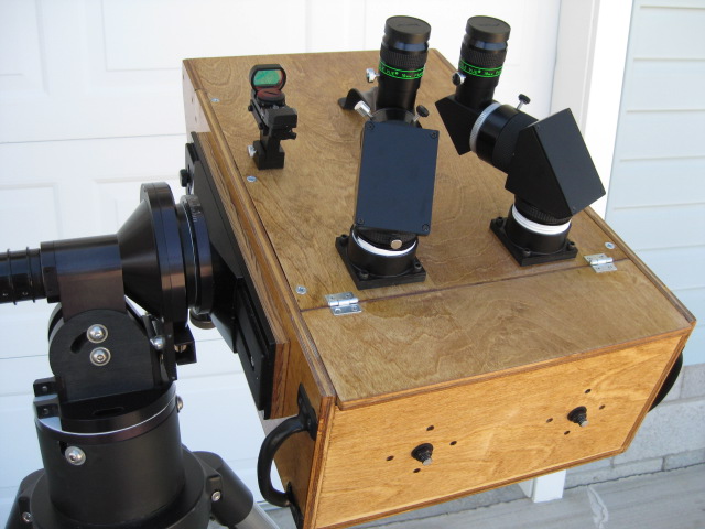
FINALLY....
Flocking, second coat Urathane, assembly and collimation done.
Flocking, second coat Urathane, assembly and collimation done.
Attached Thumbnails
#72
Mr. Bill
-
-
topic starter
- Posts: 9,823
- Joined: 09 Feb 2005
Cosmos
Posted 05 July 2012 - 02:24 PM
Front view....
Attached Thumbnails
#73
Mr. Bill
-
-
topic starter
- Posts: 9,823
- Joined: 09 Feb 2005
Cosmos
Posted 05 July 2012 - 02:25 PM
Collimation made easy with access holes...man, it's DARK down there.

Attached Thumbnails
#74
Mr. Bill
-
-
topic starter
- Posts: 9,823
- Joined: 09 Feb 2005
Cosmos
Posted 05 July 2012 - 02:26 PM
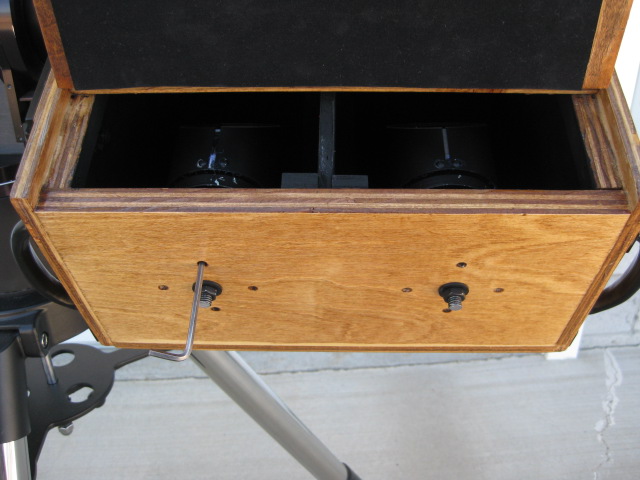
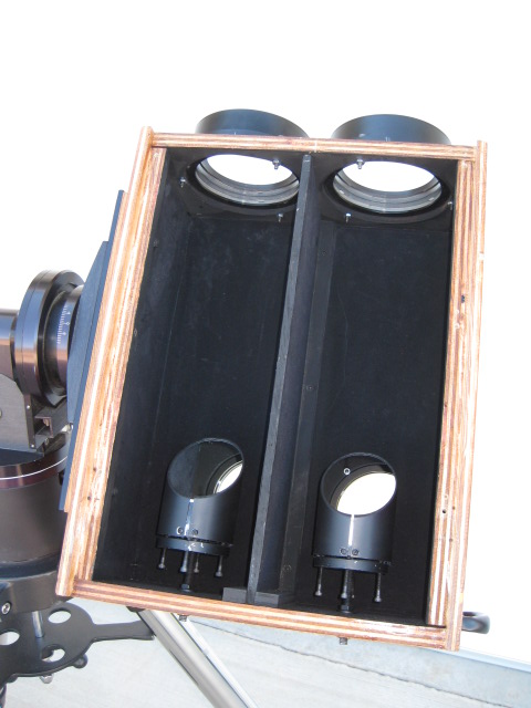
Inside Bino Box...flocking done with sheets of Edmund Optics flocking paper glued with thinned down wood glue.
Attached Thumbnails
#75
Mr. Bill
-
-
topic starter
- Posts: 9,823
- Joined: 09 Feb 2005
Cosmos
Posted 05 July 2012 - 02:49 PM
A "tip of the hat" to EE Barnard...
Attached Thumbnails

CNers have asked about a donation box for Cloudy Nights over the years, so here you go. Donation is not required by any means, so please enjoy your stay.

Recent Topics
-

-
44parts Sun mosaic (H-alpha) + AR3664 on May 11th, 2024
AstroTafelberg - Today, 11:13 AM
Solar Observing and Imaging
-
 2 notable features at the terminator at 16% crescent: Rheita E and Burckhardt
CHnuschti - Today, 11:02 AM
Lunar Observing and Imaging
-
-
-
Staying with the old or getting something new.
FCervini - Today, 10:33 AM
Beginners Forum (No Astrophotography)
-
 Canon T8i shutter failure
EricTheCat - Today, 10:28 AM
DSLR, Mirrorless & General-Purpose Digital Camera DSO Imaging
-

-

-